Chapter 10
·
Sections 1001–1017
〰️ Traps & Interceptors
Traps & Interceptors
Chapter 10 covers traps — the water seal that blocks sewer gas, their required protection by vent pipes, prohibited designs, and seal depth — and interceptors required wherever industrial waste, grease, or food waste could obstruct the drainage system or endanger the public sewer (industrial clarifiers, slaughterhouses, auto wash racks, grease traps, and sand interceptors).
💧 51–102mm Trap Seal
🚫 S-Trap Prohibited
🍽️ Grease Interceptors Required
🏭 Industrial Interceptors
§ 1001
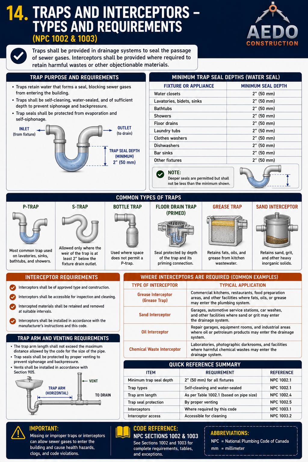
Traps Required
Every fixture connected to a drainage system must have a trap
Mandatory
Safety — Sewer Gas
Each fixture directly connected to the drainage system shall be equipped with a water-seal trap. No fixture shall be double-trapped.
Every single plumbing fixture — lavatory, WC, shower, floor drain, sink — needs its own trap between it and the drain pipe. You cannot put two traps in series on one fixture (double-trapping creates air pockets that destroy both seals).
Sewer gases — including hydrogen sulfide (H₂S), methane, and ammonia — are toxic and explosive. The water-filled trap is the only physical barrier between the open drain and the living space. Remove the trap or allow its seal to evaporate, and gas enters the building.
In Philippine bathroom renovations, plumbers sometimes skip traps on floor drains to save cost — especially in older walk-in shower conversions. This is a direct code violation and health hazard. Always verify floor drain traps are present before closing up floors.
How a trap works
P-trap water seal blocks sewer gas. Minimum seal depth 51mm, maximum 102mm (§1005). Every fixture trap must be protected by a vent pipe to prevent siphonage and back-pressure (§1002). (NPC §1001/§1005)
§ 1002
Traps Protected by Vent Pipes
Every trap must be protected against siphonage and back-pressure by a venting system
Mandatory
Seal Protection
Each fixture trap shall be protected against siphonage and back-pressure by means of a venting system installed in accordance with the requirements of Chapter 9 of this Code.
A trap by itself only holds back sewer gas under static (no-flow) conditions. The moment water moves through the connected drain piping, pressure changes (vacuum from a fast-draining fixture upstream, or back-pressure from flow in a stack) can pull or push the seal out unless the trap is vented per Chapter 9.
Venting equalizes air pressure on both sides of the trap seal as water flows. Without a vent, the seal is only protected at rest — exactly when it is needed most (during and right after a flush or drain event) it has no protection.
Vent protects the trap
Every fixture trap must be vented per Chapter 9 to prevent siphonage and back-pressure from destroying the water seal. (NPC §1002)
§ 1003
Traps Described
What an approved trap is — design and construction requirements
Design Requirements
Every trap shall be self-cleaning. Trap seals shall be designed and constructed so that they are not subject to siphonage or back-pressure, and shall be set true to their seal with respect to the fixture connection. No fixture shall be double-trapped, and traps shall have a smooth interior waterway free of internal partitions, except as approved for special interceptors.
- Self-cleaning interior — no internal pockets or ledges that retain solids
- Set level and true to its seal at installation
- No double-trapping of a single fixture
- The integral trap built into a water closet bowl is an approved trap for that fixture
A trap with internal partitions or rough interior surfaces collects solids that reduce the effective seal depth over time and create odors even while the water seal nominally remains intact.
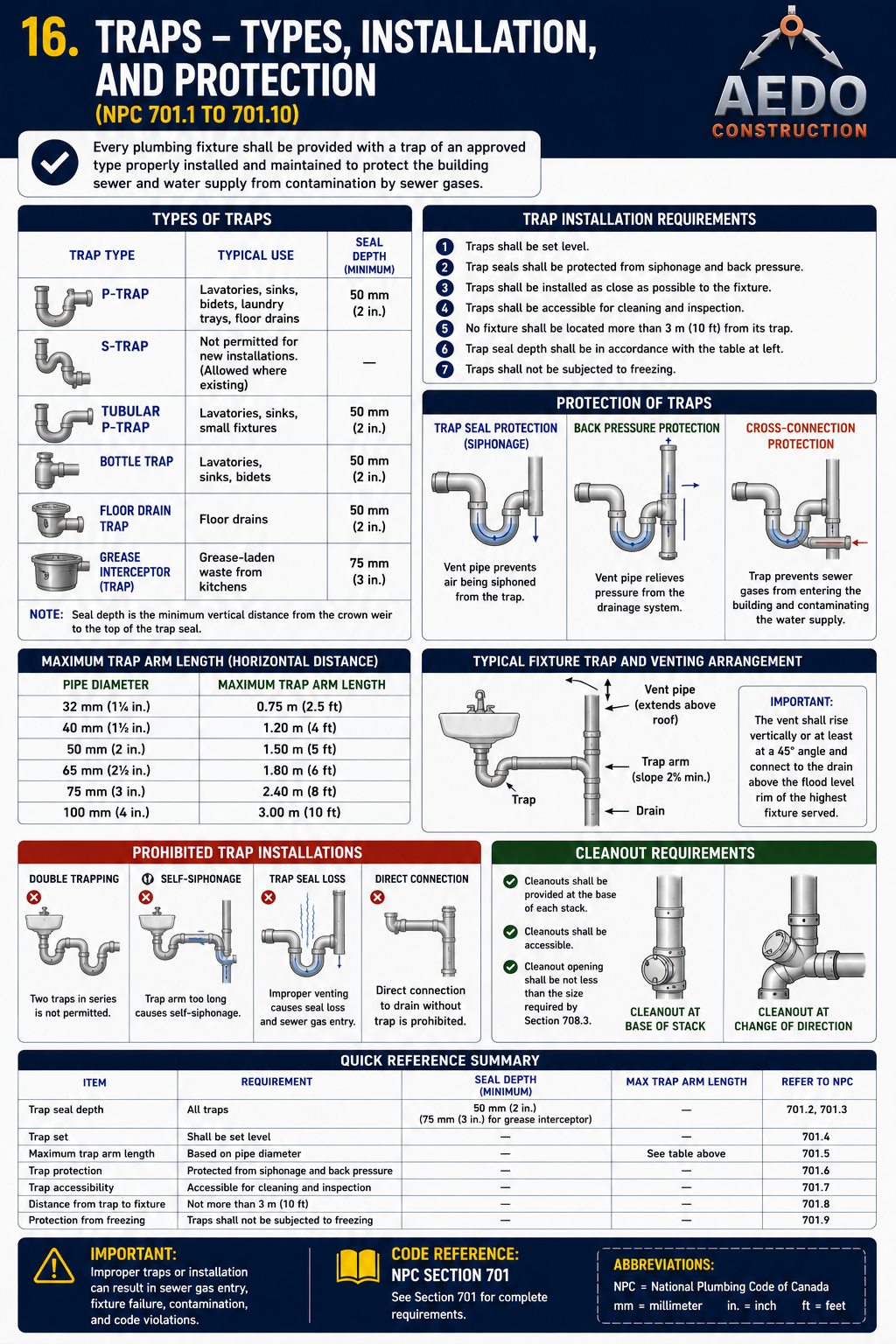
§ 1004
Traps Prohibited
Trap designs that are banned — and why each one fails
Safety — Seal Loss
Prohibited
Trap types — approved vs. prohibited: P-trap (most common, approved — self-cleaning, consistent 51–102mm seal); S-trap (prohibited — self-siphons); bottle trap, floor drain trap, grease trap, sand interceptor. Minimum seal depth per §1005: 51mm for all fixture types. Interceptors shall be accessible for cleaning and retention of harmful materials. (NPC §1004 / §1005)
Prohibited Traps — §1004
S-Trap — self-siphons when fixture drains fast
Bell Trap / Bucket Trap — shallow seal evaporates within days
Drum Trap — solids collect at bottom, not self-cleaning
Running Trap (double trap) — air pocket trapped between two seals destroys both
Crown-vented trap — vent connects at top of trap, air path destroys seal
Trap with interior partitions — flow obstructions cause deposit buildup
Approved Trap
P-Trap (only) — the standard for all fixtures
Consistent 51–102mm seal depth (§1005)
Self-cleaning — smooth interior, no obstructions (§1003)
Smooth interior radius — no 90° internal turns
Single-trap per fixture only — no double trapping
Water closet: integral trap in bowl is approved
S-Traps in Philippine Construction: S-traps were the standard configuration in Filipino plumbing for decades — many pre-2000 buildings still have them. If you see a trap pipe that goes straight down from the fixture outlet and the trap curves downward (not toward the wall), it is an S-trap. Under the NPC, these should be replaced during any renovation. The fix is simply to reconfigure the drain arm to run toward the wall and connect a P-trap.
§ 1005
Trap Seals
The water seal must be exactly the right depth — too shallow or too deep both cause problems
Key Dimension
51mm min · 102mm max
💧
Critical Rule — §1005
Trap seal depth: minimum 51mm · maximum 102mm, measured between the crown weir and the top dip of the trap
Each fixture trap shall have a water seal of not less than 51 millimetres (2 inches) and not more than 102 millimetres (4 inches), measured between the crown weir and the top dip of the trap, except where a deeper seal is found necessary by the Administrative Authority for special conditions.
The trap must hold a column of water at least 51mm deep. This depth provides enough pressure to resist both siphonage (vacuum pulling seal out) and back-pressure (gas pressure pushing through seal). More than 102mm creates too much resistance to self-cleaning flow.
A 51mm water column exerts enough pressure to resist normal sewer gas pressure fluctuations. Too shallow and any pressure differential destroys the seal. Too deep and solids collect in the trap bottom.
Seal depth reference
Too shallow (<51mm) = seal easily lost. Correct (51–102mm) = adequate pressure. Too deep (>102mm) = solids collect at bottom, trap clogs. (NPC §1005)
Common Violations — §1005 Trap Seals
✗
Bell-trap / bucket trap (pre-1990s construction)
These loose-cup traps rely on a water seal that evaporates within days in a dry floor drain. Common in older Philippine commercial buildings.
Replace with deep-seal P-trap with primer or install drain cover
✗
Unused floor drain with no water seal (dry trap)
Infrequently-used floor drains in storage rooms, utility rooms, and parking areas dry out. No water = no seal = sewer gas entry. See §1006 / §1007 for floor drain trap and seal-protection requirements.
Install trap primer, glycol-filled trap, or deep-seal floor drain rated for infrequent use
✗
Shallow chrome P-trap set too high
Cheap chrome P-traps can have seal depths below 51mm if installed with the outlet too close to the trap weir level.
Verify seal depth with ruler when installing — PVC P-traps are more consistent
§ 1006
Floor Drain Traps
Floor drains must have an integral or attached trap with an accessible, removable strainer
Mandatory
Each floor drain shall be provided with a trap, either integral with the drain body or installed in the branch serving it. The floor drain strainer shall be removable to allow cleaning and rodding of the trap and drain line. Floor drains installed in waterproofed floors shall be set with a clamping device or flange to maintain the integrity of the waterproofing membrane.
Floor drains are the fixture type most prone to dry-trap problems because they are used infrequently. A trap that cannot be easily accessed and re-primed compounds the seal-loss problem described in §1005 and §1007.
§ 1007
Trap Seal Protection
Maintaining the seal on traps subject to infrequent use or evaporation
🛡️
Protection Rule — §1007
Traps subject to evaporation (infrequently-used floor drains, etc.) shall be protected against loss of seal by an approved trap-seal primer or equivalent device
Floor drains and other traps that are not used regularly enough to keep the seal replenished by normal use shall be fitted with an automatic trap primer, or another Administrative-Authority-approved method, to maintain the water seal and prevent sewer gas from entering the building.
In the Philippines, infrequently-used floor drains in utility rooms, parking levels, and storage areas are the most common source of dry-trap sewer-gas complaints. Specify trap primers tied to a nearby fixture's supply line (or an automatic timed primer) at design stage rather than relying on maintenance staff to manually pour water periodically.
§ 1008
Industrial Interceptors (Clarifiers) and Separators
Industrial and harmful wastes must be intercepted before entering the drainage system
Industrial wastes that may damage the drainage system, the public sewer, or a wastewater treatment process — including harmful solids, settleable solids, or substances that could obstruct or corrode piping — shall pass through an approved interceptor or clarifier before discharge to the building drainage system.
Purpose
Remove harmful or settleable solids and substances from industrial waste before it reaches the building drain.
Access
Interceptors/clarifiers shall be located and constructed to be readily accessible for inspection and cleaning.
Venting
Where required by the nature of the waste, the interceptor shall be vented to prevent accumulation of gases.
§ 1009
Slaughter Houses, Packing Establishments, Etc.
Special interceptor requirements for slaughterhouse and meat-packing waste
Waste from slaughterhouses, meat-packing establishments, and similar operations — containing blood, viscera, hair, feathers, and other solids — shall be passed through an interceptor designed to retain such solids before discharge to the building drainage system or public sewer.
Untreated slaughterhouse waste rapidly fouls and obstructs ordinary drainage piping and can overwhelm public sewer and treatment systems. The interceptor required by this section is in addition to, and distinct from, the industrial interceptor described in §1008.
§ 1010
Minimum Requirements for Auto Wash Rack
Vehicle wash facilities must intercept sand, grit, and oil before discharge
Drainage from automobile wash racks shall be passed through an approved sand/oil interceptor before connecting to the building drainage system. The interceptor shall be sized to retain sand, grit, and free oil carried by the wash-down water and shall be accessible for regular cleaning.
What It Catches
Sand, grit, and free oil from vehicle undercarriage and engine wash-down.
Access
Readily accessible for periodic removal of accumulated sediment and oil.
Maintenance
Must be cleaned on a schedule — an interceptor full of sediment stops working.
§ 1011
Grease Traps
Required where greasy waste enters the drainage system
A grease trap is required wherever fats, oils, and grease (FOG) can enter the drainage system from food-preparation fixtures. It separates grease so it cannot solidify and clog the building drain or the public sewer.
What Connects
Pot/pan sinks, pre-rinse sinks, scullery sinks, dishwashers, wok ranges, and floor drains in cooking areas.
What Must Not
Toilets and other sanitary (excreta) waste shall never pass through a grease trap.
Sizing
Sized by the number of fixtures connected and required rate of flow (Table 10-2).
Access
Located to be readily accessible for regular cleaning and grease removal.
Table 10-2 — Grease Trap Sizing
| Total Number of Fixtures Connected | Required Rate of Flow (L/min) | Grease Retention Capacity (kg) |
|---|
| 1 | 76 | 18 |
| 2 | 95 | 23 |
| 3 | 132 | 32 |
| 4 | 189 | 45 |
Values per NPC Table 10-2 (p.112) — metric fixture-count basis.
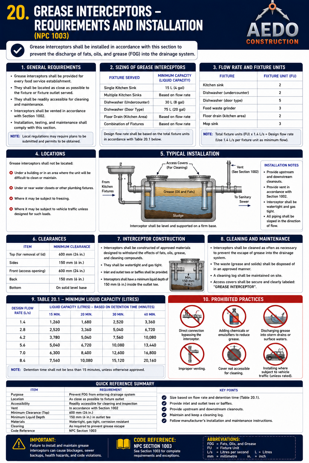
Grease trap — requirements & installation. General requirements, sizing by fixtures served and minimum liquid/grease retention capacity (Table 10-2), typical installation between the kitchen fixtures and the sanitary sewer, required clearances, construction, regular cleaning/maintenance, and prohibited practices.
Restaurant compliance: A missing or undersized grease trap is one of the most common reasons a food establishment fails plumbing and sanitary inspection. Coordinate with
Chapter 8 for kitchen equipment that must instead drain
indirectly.
§ 1012
Grease Interceptors for Commercial Kitchens
Larger-scale grease interception for hotels, canteens, and commercial food establishments
Commercial kitchens — including those in hotels, restaurants, canteens, and food-processing establishments — that generate higher volumes of greasy waste shall install a grease interceptor sized for the establishment's total kitchen fixture load, in addition to (or in place of) the smaller grease traps described in §1011, as required by the Administrative Authority.
A single point-of-use grease trap (§1011) is adequate for a small kitchen, but a hotel or large commercial kitchen with many simultaneous fixtures requires a larger, centrally-located interceptor to handle the combined peak flow and grease load without overflowing.
§ 1013
Food Waste Disposal Prohibited
Food waste grinders shall not discharge through a grease trap or interceptor
🚯
Prohibition — §1013
Waste from a food-waste grinder (garbage disposal) shall not be discharged through, or connected to, a grease trap or grease interceptor
Ground food solids rapidly fill and foul a grease interceptor's retention capacity, defeating its purpose of separating only fats, oils, and grease. Food-waste grinder discharge must instead connect directly to the sanitary drainage system, sized to handle the solids load.
📐 NPCP Reference Diagrams
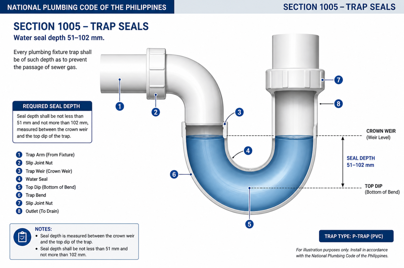
NPCP §1005 — Trap seals. Every fixture trap shall have a water-seal depth between 51 mm and 102 mm, measured between the crown weir and the top dip of the bend, to prevent the passage of sewer gas.
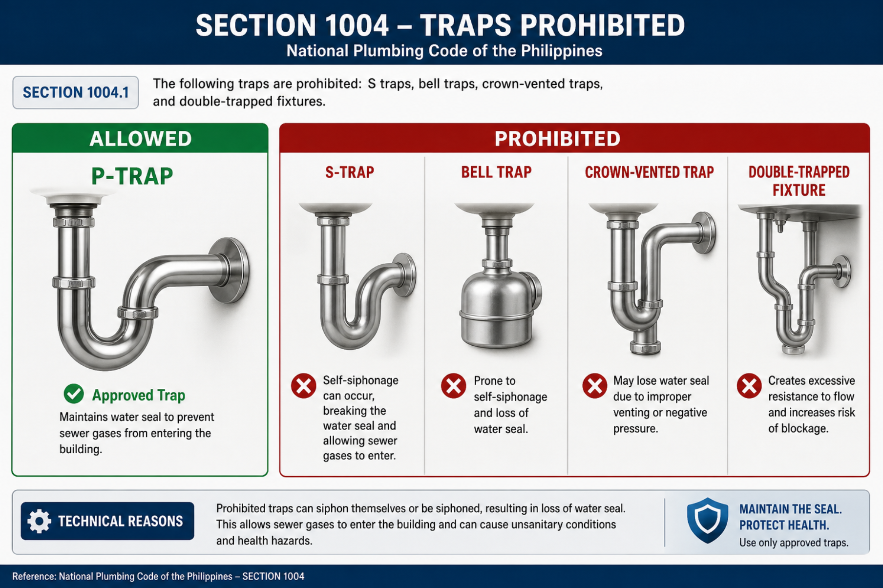
NPCP §1004 — Prohibited traps. The P-trap is approved; S-traps, bell traps, crown-vented traps, and double-trapped fixtures are prohibited because they self-siphon or lose the water seal.
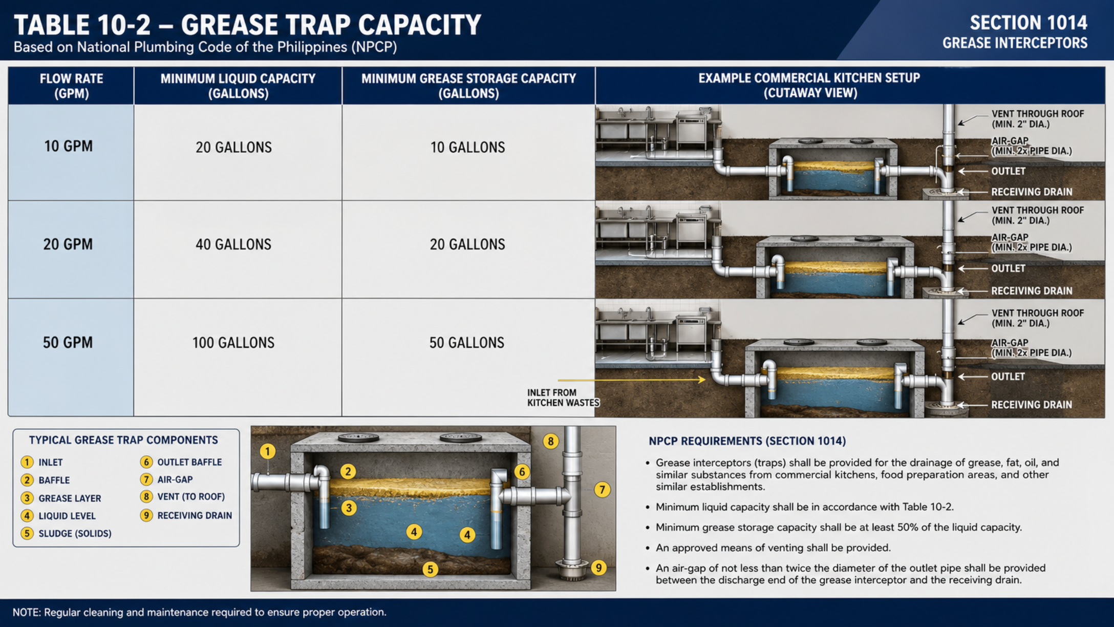
NPCP §1014 / Table 10-2 — Grease interceptor capacity. Minimum liquid and grease-storage capacity sized by flow rate (e.g. 10 GPM → 20 gal; 50 GPM → 100 gal), with an air gap to the receiving drain.
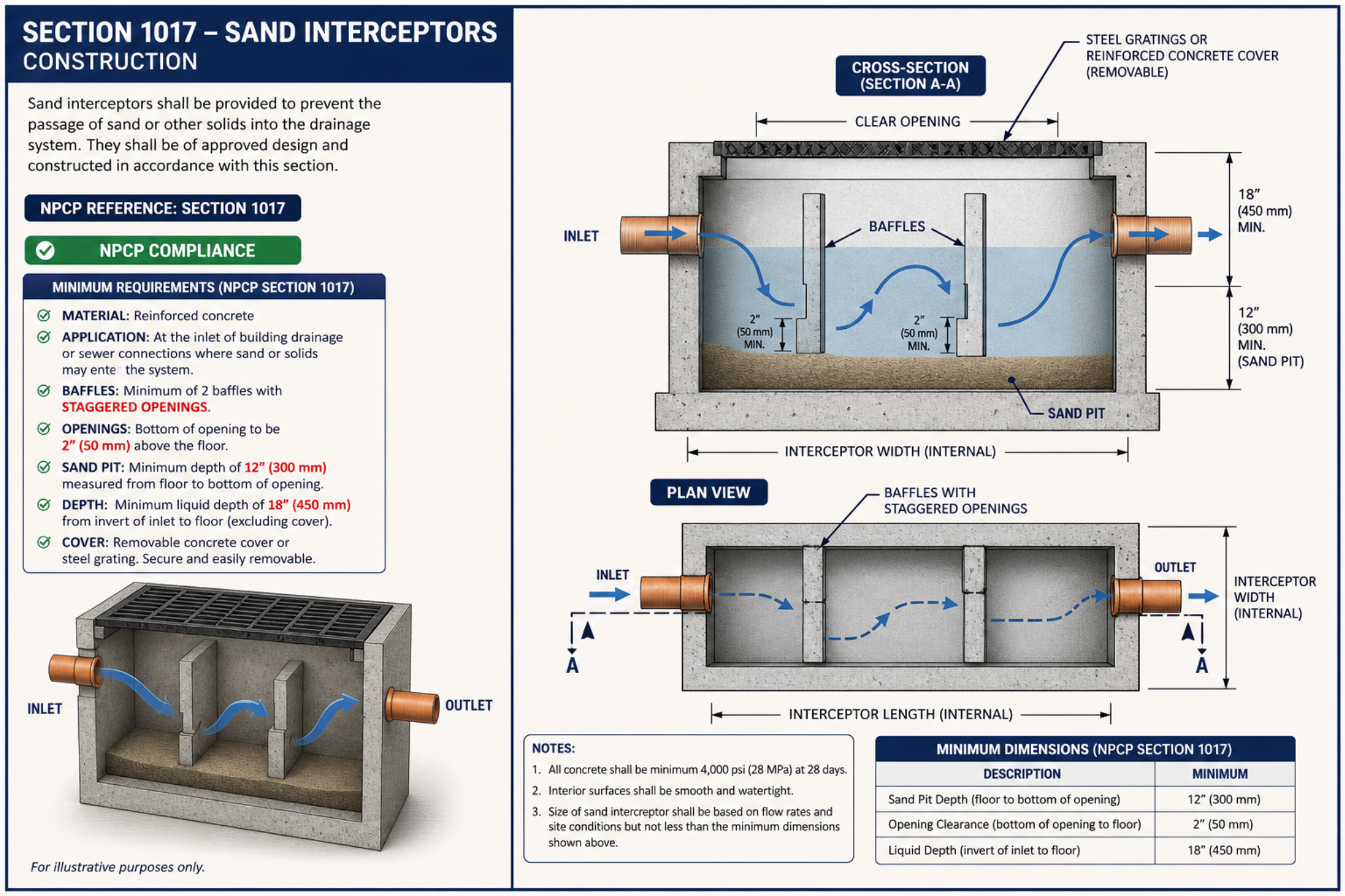
NPCP §1017 — Sand interceptors. Reinforced-concrete interceptor with staggered baffles and a sand pit to trap sand and solids before discharge — for garages, car-wash bays, and industrial floors.