
Chapter 3 · General Regulations
GENERAL REGULATIONS Sections 301–316
Chapter 3 sets the fundamental technical rules that apply to all plumbing work. The two most cited rules: §302 grade of horizontal drainage piping (minimum slope) and §303 changes in direction of drainage flow (approved bend angles and fittings). Also covers required sewer/system connections, prohibited fittings and practices, protection of piping, hangers/supports, and trenching.
§301
General
NPC 2000 · Chapter 3 · Section 301
Code Requirement
301.1
Plumbing systems shall be designed, constructed, and maintained in a manner that protects public health and safety, using approved materials, installation methods, and workmanship that conform to this Code.
§301 sets out the chapter's general intent. Material standards and approved pipe materials are detailed in Chapter 14 (Materials); the specific technical rules of this chapter follow in §302–§316.
§302
Grade of Horizontal Drainage Piping
NPC 2000 · Chapter 3 · Section 302 · ★ Exam Essential
Code Requirement
302.1
Horizontal drainage piping shall be run in practical alignment and at a uniform grade of not less than ¼ inch per foot (2%, or 20 mm/m) toward the point of disposal.
302.2
Where it is impractical, due to the depth of the street sewer, structural features, or adverse arrangement of a building, to obtain a slope of 20 mm/m for pipe 102 mm in diameter or larger, the Administrative Authority may approve a lesser slope, provided the required velocity for self-cleansing flow is maintained.
Grade Requirements
General minimum grade2% (20 mm/m)
Equivalent¼ in / ft
Reduced-grade exceptionPipe ≥ 102 mm, w/ Admin. Authority approval
Pipe Grade Diagram — §302
Practical Grade Reference Table
| Pipe Size | Min Grade | Drop per 1 m | Drop per 3 m | Equivalent |
|---|---|---|---|---|
| 50 mm (2 in) | 2% | 20 mm | 60 mm | ¼ in / ft |
| 75 mm (3 in) | 2% | 20 mm | 60 mm | ¼ in / ft |
| 102 mm (4 in) | 2% (or less, if approved) | 20 mm | 60 mm | ¼ in / ft |
| 150 mm (6 in) | 2% (or less, if approved) | 20 mm | 60 mm | ¼ in / ft |
| 200 mm (8 in) | 2% (or less, if approved) | 20 mm | 60 mm | ¼ in / ft |
Image needed — [CH3-DIAGRAM-A]: Rendered isometric view of a building's horizontal drain branch showing the standard 2% grade, with dimension triangles, pipe size callouts, and a level reference line.
§303
Changes in Direction of Drainage Flow
NPC 2000 · Chapter 3 · Section 303 · ★ Exam Essential
Code Requirement
303.1
Changes in direction of drainage flow shall be made by the use of appropriate drainage fittings only, including 22½°, 45°, and 60° bends, wyes, and approved combination fittings.
303.2
Horizontal to Vertical: Use a wye (Y), combination Y and ⅛ bend, or sanitary tee (T) branch for waste connections only.
303.3
Vertical to Horizontal: Use a long-sweep ¼ bend, combination Y and ⅛ bend, or approved offset. Standard (short-sweep) 90° bends are not permitted for this transition.
303.4
Double sanitary tee installations on a vertical stack are sized per the nominal pipe diameters: 51, 63, 76, 89, 102, 114, 127, and 152 mm.
Approved Fittings Summary
Permitted bend angles22½° · 45° · 60°
Horiz → VerticalWye, San. T
Vertical → HorizLong-sweep ¼ bend
Double san. tee sizes51–152 mm
Approved vs. Prohibited Fittings — §303
Approved fitting
Prohibited fitting
Key dimension
Image needed — [CH3-DIAGRAM-B]: Rendered isometric or plan-view drawing of a complete drain branch showing 45° wye entry, long-sweep bends, and sanitary tee — with "prohibited" alternatives shown in red for comparison.
§304
Connections to Plumbing System Required
NPC 2000 · Chapter 3 · Section 304
Code Requirement
304.1
Every plumbing fixture, drain, appliance, and appurtenance that receives or discharges liquid wastes shall be properly connected to the drainage system of the building.
304.2
No fixture shall discharge into a yard, court, or street without being properly piped and connected to the approved sanitary drainage system.
§305
Sewer Required
NPC 2000 · Chapter 3 · Section 305
Code Requirement
305.1
Every building intended for human occupancy on a property where a public sewer is available within a reasonable distance shall connect its building sewer to the public sewer.
305.2
Where a public sewer is not available, the building shall make suitable provision for disposing of the building sewage, via an approved private sewage disposal system (septic tank with absorption field), per Appendix B.
Sewer Connection Rule
Public sewer available→ Connect to it
No public sewer→ Private system (App. B)
§306
Damage to Drainage System or Public Sewer
NPC 2000 · Chapter 3 · Section 306
Code Requirement
306.1
No person shall deposit into the drainage system or public sewer any ashes, cinders, solids, rags, or flammable, poisonous, or explosive liquids, or any other substance that may damage the system or its operation.
306.2
Roofs, inner courts, vent shafts, areaways, or other open spaces shall not be connected to the soil and waste pipe systems.
§307
Industrial Wastes
NPC 2000 · Chapter 3 · Section 307
Code Requirement
307.1
Industrial wastes deleterious to the public sewer system shall be treated before discharge to remove or neutralize substances injurious to the sewer, treatment plant, or receiving waters.
307.2
Wastes that may affect surface or subsurface waters require an acceptable form of treatment before discharge to the ground or a waterway.
Common Industrial Waste Interceptors
| Type | Application | Removes |
|---|---|---|
| Grease Interceptor | Restaurants, commercial kitchens | Fats, oils, grease (FOG) |
| Oil/Sand Separator | Garages, auto shops, car wash | Petroleum, silt, sand |
| Acid Neutralizer | Laboratories, hospitals | Acidic / alkaline waste |
§308
Location
NPC 2000 · Chapter 3 · Section 308
Code Requirement
308.1
Excreta and drainage systems shall not be located in any lot other than the lot on which the building they serve is sited.
308.2
Subsequent subdivision of a property shall not be permitted to decrease the required clearances or access to any part of an existing plumbing or drainage system.
§309
Improper Location
NPC 2000 · Chapter 3 · Section 309
Code Requirement
309.1
Piping and equipment shall not be located where they would interfere with the normal operation of a fixture, or with the operation of a window or door, or restrict required access to any facility.
§310
Workmanship
NPC 2000 · Chapter 3 · Section 310
Code Requirement
310.1
All work shall conform to accepted engineering practice. Piping shall be run in straight lines and at exact grades wherever possible.
310.2
Concealing defects in pipe or fittings by welding, brazing, soldering, or coatings is prohibited.
310.3
All pipe ends shall have burrs removed and shall be reamed to the full bore of the pipe.
Workmanship & support of plumbing systems (§310). Piping run in straight, properly graded lines with no concealed defects; pipe ends reamed free of burrs to the full bore before joining.
§311
Prohibited Fittings & Practices
NPC 2000 · Chapter 3 · Section 311
Prohibited Items
311.1
The following shall not be used as a drainage fitting: double hub fitting for a lead-caulked joint in vertical position; single or double tee branch; single or double tapped tee branch; side inlet quarter bend; running thread; and band or saddle.
311.2
Exception: A double hub sanitary tapped tee may be used on vertical lines as a fixture connection.
311.3
Drainage piping shall not be drilled or tapped, and a vent pipe shall not be used to serve as a soil or waste pipe.
Prohibited Fittings (§311.1)
| Fitting / Practice | Status |
|---|---|
| Double hub fitting, lead-caulked joint, vertical position | ❌ Prohibited |
| Single or double tee branch | ❌ Prohibited |
| Single or double tapped tee branch | ❌ Prohibited |
| Side inlet quarter bend | ❌ Prohibited |
| Running thread | ❌ Prohibited |
| Band or saddle | ❌ Prohibited |
| Double hub sanitary tapped tee (vertical, fixture connection) | ✅ Exception — allowed |
§312
Independent System
NPC 2000 · Chapter 3 · Section 312
Code Requirement
312.1
Every building's drainage system shall be separate and independent.
312.2
Exception: A rear building may connect through the front building's drain, provided the drain is of adequate size for both buildings and gravity flow to the public sewer or disposal point is not impaired.
This rule prevents one building's drainage problem (blockage, surcharge) from affecting another building, except in the narrow rear-building exception above.
§313
Repairs and Alterations
NPC 2000 · Chapter 3 · Section 313
Code Requirement
313.1
Existing plumbing systems undergoing repair or alteration may deviate from current Code requirements where strict compliance is impractical, subject to approval by the Administrative Authority.
313.2
Existing building sewers or drains reused in new work shall be tested and found to conform to the requirements governing new construction.
313.3
All abandoned openings in the system, except vent terminals, shall be permanently plugged or capped.
Deviations Subject to Approval
Reused Sewers Must Test to New-Work Standard
Openings Capped (except vent terminals)
§314
Protection of Piping, Materials & Structures
NPC 2000 · Chapter 3 · Section 314 · ★ Exam Essential
Code Requirement
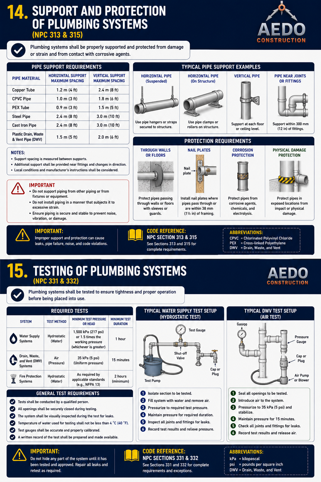
314.1
Pipe passing under or through a wall shall be protected by a metal sleeve; underground piping shall be protected with a polyethylene sheath where subject to corrosion.
314.2
Hot water piping shall be provided with expansion provision. No pipe shall be embedded directly in concrete or masonry without a protective sleeve.
314.3
Where a trench runs parallel to a building wall, the trench bottom shall not break through a plane sloped at 45 degrees from the bottom of the building's foundation.
314.4
No building sewer or other drainage piping shall be installed under or within 0.6 meter of any building or structure, nor less than 0.3 meter below finished ground level.
Key Clearances
Sewer clearance from structure≥ 0.6 m
Min. cover below grade≥ 0.3 m
Trench-bottom angle limit45°
Pipe through wallMetal sleeve
§315
Hangers and Supports
NPC 2000 · Chapter 3 · Section 315
Code Requirement
315.1
All piping shall be supported at intervals sufficient to prevent sagging, and anchored to prevent movement.
Vertical Pipe Support Intervals
| Material | Support Interval |
|---|---|
| Cast iron | Every storey |
| Threaded (screwed) pipe | Every other storey |
| Copper tubing | Every 3 meters |
| Lead pipe | Every 1.20 meters |
| Plastic pipe | Every 1 meter |
Horizontal Pipe Support Intervals
| Material | Support Interval |
|---|---|
| Cast iron | 1.5 m intervals; within 0.45 m of each hub |
| Copper tubing ≤ 38 mm | 1.8 m intervals |
| Copper tubing ≥ 51 mm | 3.0 m intervals |
§316
Trenching, Excavation and Backfill
NPC 2000 · Chapter 3 · Section 316
Code Requirement
316.1
Tunnels used in lieu of open trenching shall maintain at least 0.6 meter of clearance above the pipe, with a maximum unsupported length of 2.4 meters.
316.2
Trenches shall remain open until the piping has been inspected and tested and approved by the Administrative Authority.
316.3
Backfill shall be placed in layers not exceeding 0.3 meter, using clean earth free of stones, cinders, or other materials that could damage the pipe.
Trenching Limits
Tunnel clearance above pipe≥ 0.6 m
Max. unsupported tunnel length2.4 m
Backfill layer thickness≤ 0.3 m
Diagram Requests — Chapter 3
Images Needed for This Chapter
[CH3-DIAGRAM-A] §302 — Isometric view of a horizontal drain branch at the standard 2% grade. Include a level reference line, dimension triangles showing drop per meter, and flow direction arrows.
[CH3-DIAGRAM-B] §303 — Plan + isometric view of a drain branch junction. Show approved (45° wye, long-sweep 90°, combo Y+⅛) in green and prohibited (standard tee, short 90°) in red. Label each fitting type and bend angle.
[CH3-DIAGRAM-C] §314 — Cross-section detail of pipe through a wall/slab with a metal sleeve, plus a plan view showing the 0.6 m structure clearance / 0.3 m cover rule for building sewers.
[CH3-DIAGRAM-D] §316 — Trench cross-section showing tunnel clearance (0.6 m above pipe), maximum 2.4 m unsupported tunnel length, and 0.3 m backfill lift lines.