Plumbing Fixtures
Chapter 4 establishes standards for all plumbing fixtures — the materials they must be made of, the minimum space required around them, and crucially, the minimum number of fixtures required for every type of occupancy. Key rules include the 100mm minimum drain for water closets, required strainers on all floor drains, and waterproof shower floor requirements.
Quality and Design
Material and surface standards for all plumbing fixtures
All plumbing fixtures shall be:
Impervious, non-absorbent, and free from defects — easy to clean, no crevices where bacteria can grow.
Fixture surfaces that contact potable water or waste shall not leach harmful substances.
Ceramic vitreous china, enameled cast iron, or approved equivalent. Plastics must meet ASTM or equivalent PNS standards.
Surfaces exposed to drain water shall be resistant to household-strength acids and cleaning agents.
Prohibited Fixtures
Fixtures that shall not be installed
| Prohibited Fixture / Condition | Reason |
|---|---|
| Bell-trap floor drains | Trap seal is easily lost; allows sewer gas entry |
| S-trap water closets | Self-siphoning action destroys trap seal |
| Lead-lined fixtures | Lead can leach into water supply — toxic |
| Fixtures with non-smooth surfaces | Cannot be properly cleaned; bacterial growth risk |
| Non-approved plastics (without PNS/ASTM certification) | Unknown chemical stability and durability |
| Overflow holes below the flood level rim | Creates cross-connection — contaminates supply |
Prohibited Fixture Checker
Select a fixture or condition to verify its compliance status under §402.
Setting Fixtures — Required Clearances
Minimum clear space around fixtures for use and maintenance
| Fixture | Front Clearance | Side Clearance | Notes |
|---|---|---|---|
| Water Closet (WC) | 375 mm (centerline to side wall) | 750 mm (center-to-center, similar fixture) | Measured from fixture centerline, not front rim |
| Bidet | 375 mm (centerline to side wall) | 750 mm (center-to-center) | Same clearances as WC |
| Lavatory (Sink) | 600 mm | 150 mm min each side | Measured from front rim of basin |
| Urinal | 300 mm (centerline to side wall) | 600 mm (center-to-center) | Measured from fixture centerline |
| Bathtub | 600 mm | – | At access (non-wall) side; access panel for plumbing required |
| Shower | 0.6 m² (≥762 mm circle) | – | Minimum interior shower floor area — see §406 |
Fixture Clearance Lookup
Select a fixture type to display the required minimum clearances per §403.
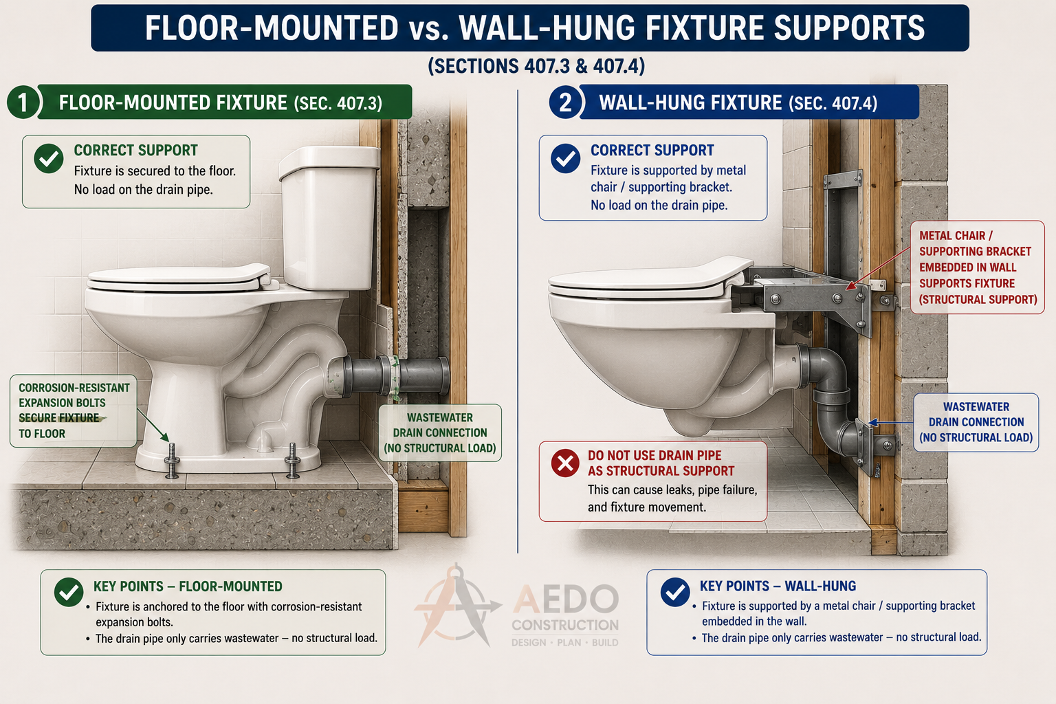
Floor-mounted WC secured to the floor with corrosion-resistant expansion bolts (left) vs wall-hung WC supported by a metal chair embedded in the wall (right). The drain pipe carries wastewater only — it bears no structural load.
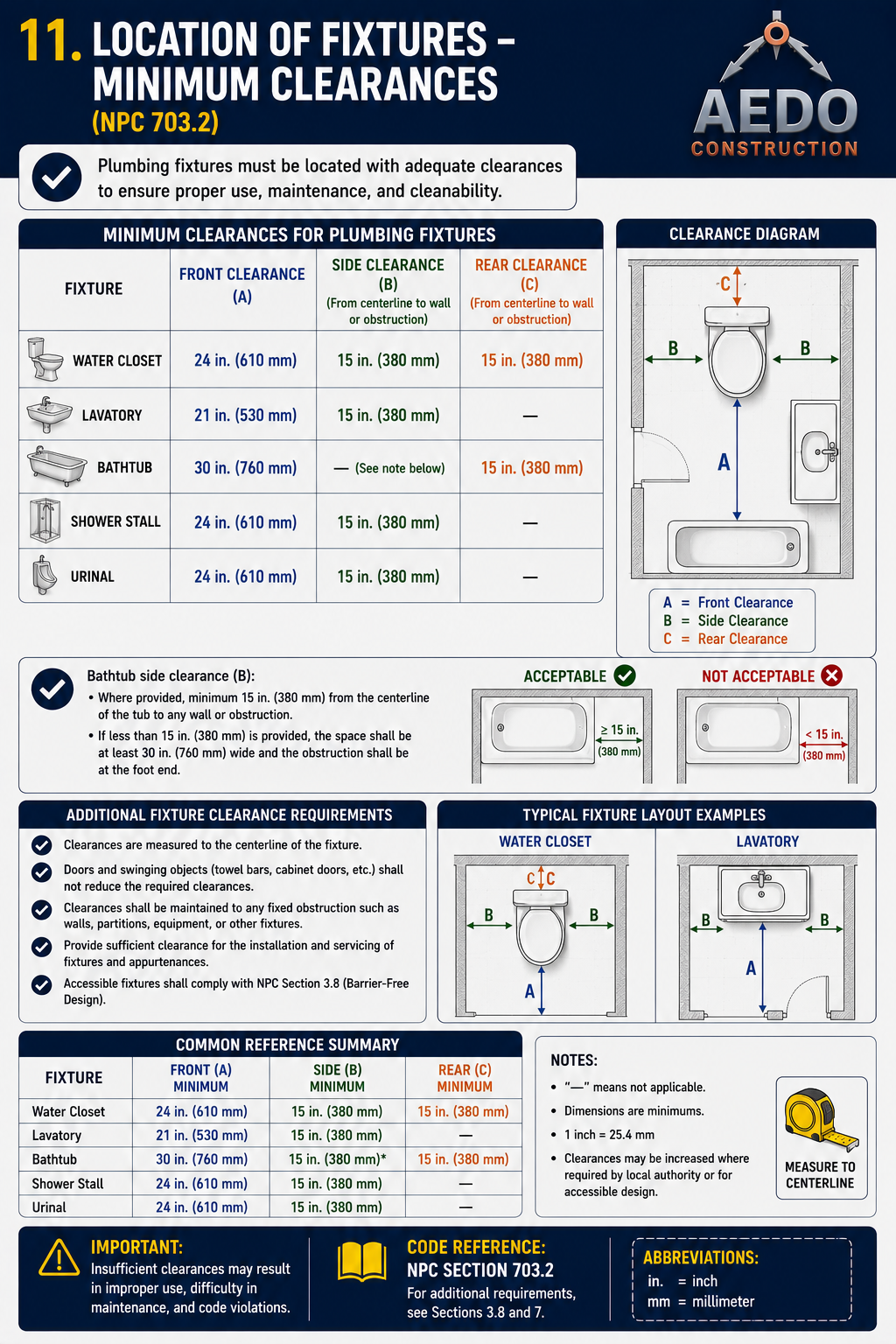
Minimum clearances for plumbing fixtures: Water Closet/Bidet — centerline to side wall ≥375mm, center-to-center ≥750mm; Urinal — centerline to side wall ≥300mm, center-to-center ≥600mm. Always measured from the fixture centerline, not the front rim.
Floor Drains
Requirements for all floor drain installations
Every floor drain shall be fitted with an approved trap. Trap seal depth per §1005: minimum 51mm, maximum 102mm.
Sized to the area served, with an approved strainer and waterstop fitted at the drain body (§409.1).
| Requirement | Specification |
|---|---|
| Drain body | Sized to area served; strainer & waterstop required |
| Trap seal depth (minimum) | 51 mm |
| Trap seal depth (maximum) | 102 mm |
| Strainer required | Yes — removable, opening ≥ area of drain pipe |
| Location | Accessible for inspection and cleaning |
| Prohibited trap type | Bell trap (shallow, loses seal easily) |
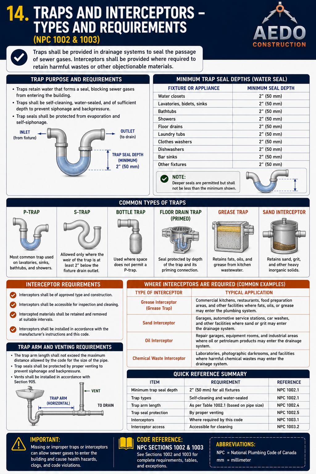
Trap types overview: P-trap (most common), S-trap (prohibited — self-siphoning), bottle trap, floor drain trap (primed), grease trap, and sand interceptor. Minimum trap seal depth: 51mm (max 102mm) for all fixtures, per §1005. Trap arm length governed by pipe size per Table 7-5.
Floor Drain Compliance Checker
Enter your floor drain specifications to check compliance with §404.
Strainers Required
Every floor drain shall be equipped with a strainer
Every floor drain, shower drain, and receptor drain shall have an approved strainer. The strainer shall:
- Be removable for cleaning without tools (where practicable)
- Have a total open area not less than the cross-sectional area of the drain pipe it serves
- Be constructed of corrosion-resistant material (stainless steel, brass, or approved plastic)
- For floor drains in public areas: strainer openings ≤ 9.5mm (3/8") in any dimension to prevent foot entrapment
Shower Floors and Receptors
Waterproofing, slope, and drain requirements for shower areas
0.6 m² interior area, large enough to encompass a 762mm diameter circle, to a height of 1.78m
2% (20mm/m) to 4% (40mm/m) slope toward drain — water must not pond
Floor and walls to min. 1.8m height — waterproof membrane or tile with waterproof grout/adhesive
Floor surface must have slip-resistance coefficient of friction ≥ 0.6 (wet)
| Shower Component | Requirement | Notes |
|---|---|---|
| Minimum floor area | 0.6 m² (≥762mm circle) | Interior clear dimension, to a height of 1.78m |
| Floor slope | 2% – 4% (20–40 mm/m) | All points drain toward outlet |
| Dam / threshold | 51–228 mm depth | At least 25.4mm lower than outside floor |
| Drain size | See §404 (Floor Drains) | — |
| Access panel | Required to trap and supply valve | From adjacent space if necessary |
Shower Floor Compliance Checker
Enter shower interior dimensions and floor slope to verify §406 compliance.
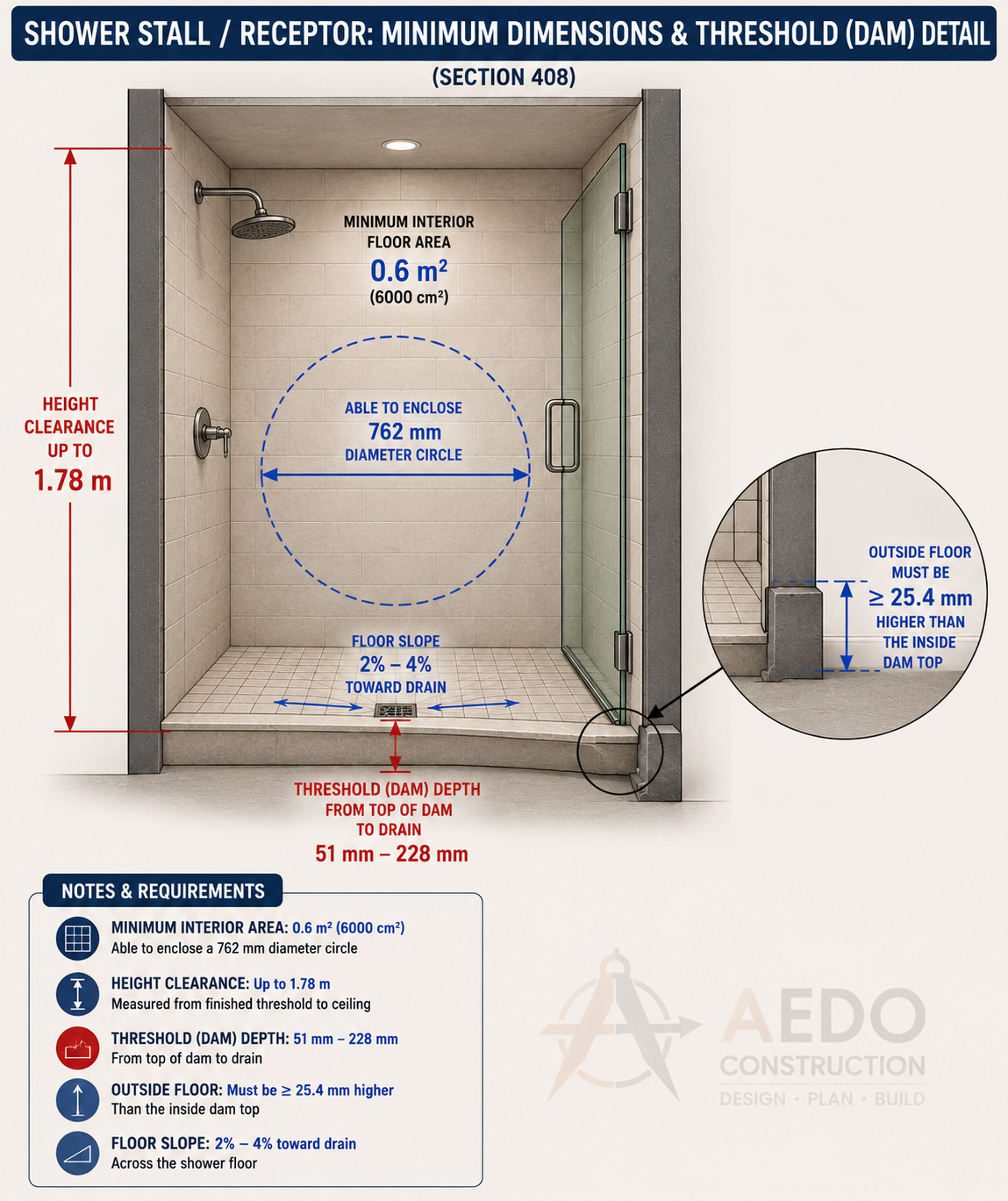
Shower stall minimum interior floor area: 0.6 m² (able to enclose a 762mm diameter circle). Height clearance minimum 1.78m. Floor slope 2–4% toward drain. Threshold (dam) depth: 51–228mm from top of dam to drain.
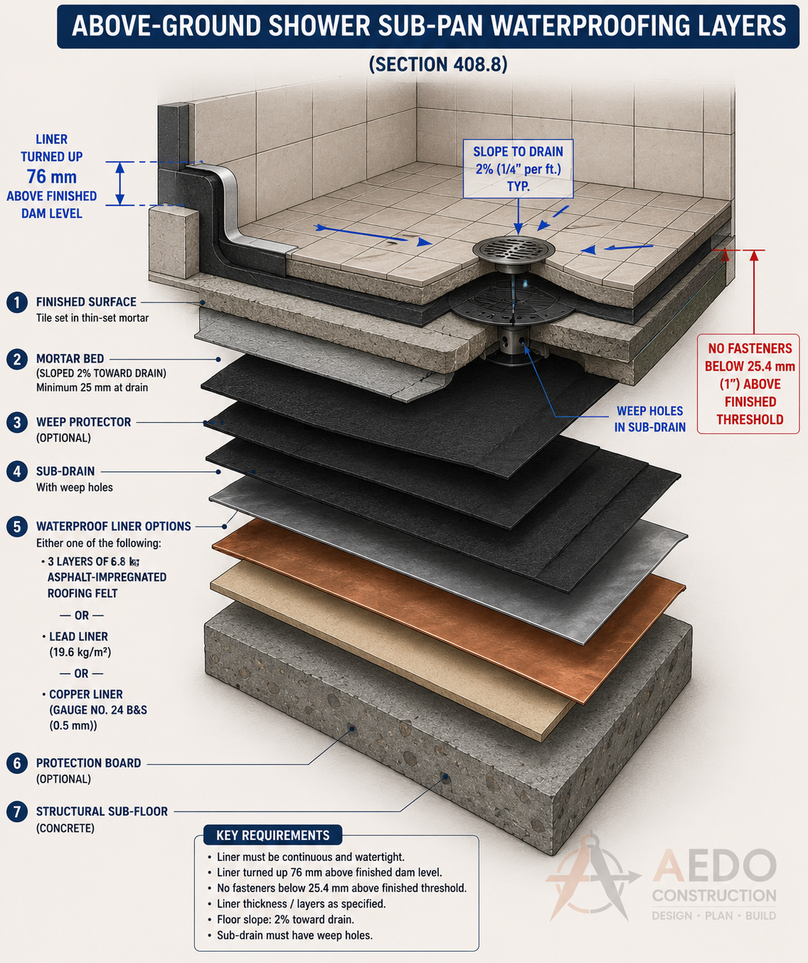
Shower sub-pan waterproofing assembly cross-section: liner turned up 76mm above finished dam level, mortar bed sloped 2% toward drain, weep holes in sub-drain, and waterproof membrane below tile finish. No fasteners below 26.4mm above finished threshold.
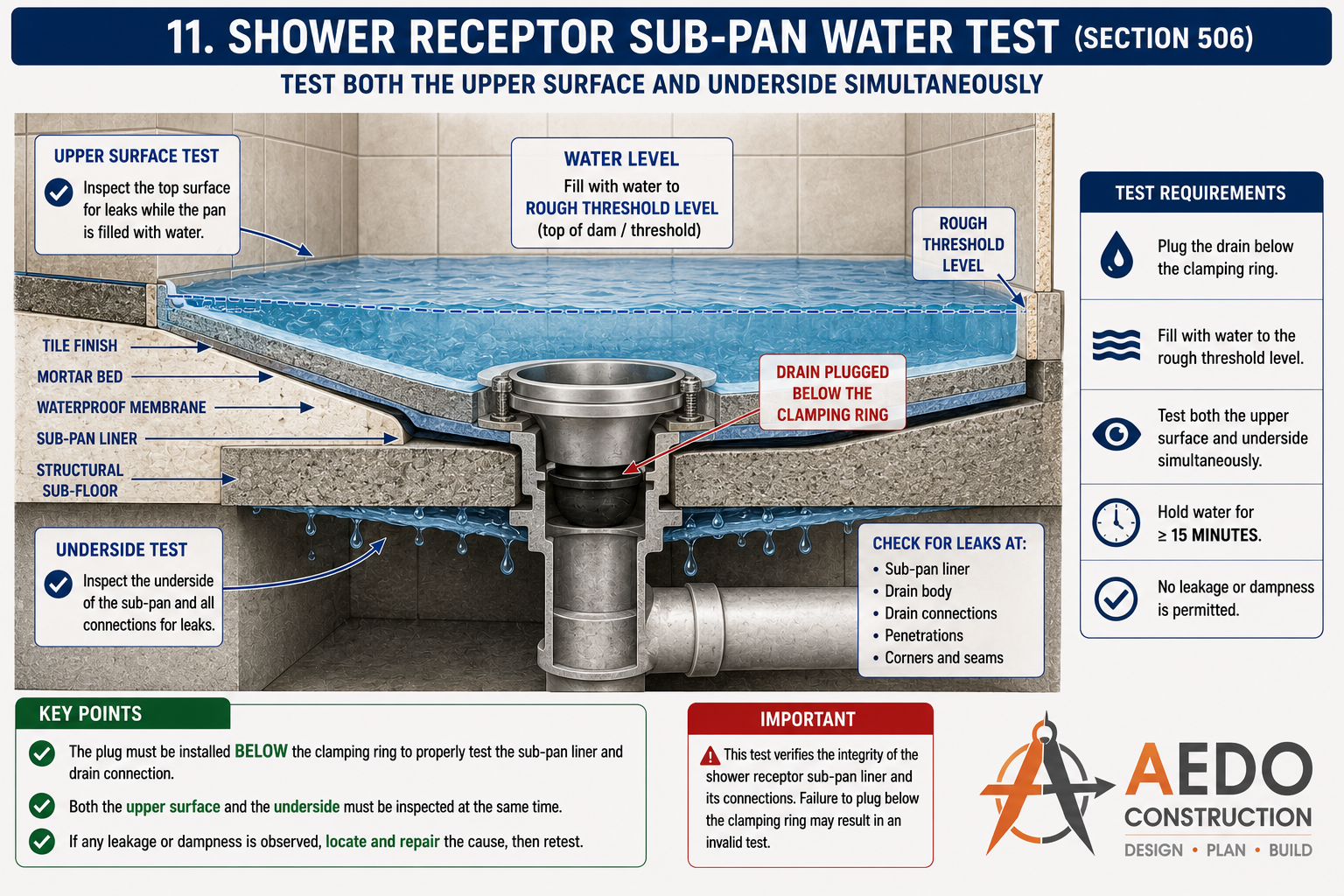
Shower receptor sub-pan water test (NPC §506). Plug the drain below the clamping ring, fill to the rough threshold level, and test the upper surface and underside simultaneously. Hold for a minimum of 15 minutes — no leakage or dampness is permitted. Check for leaks at the sub-pan liner, drain body, drain connections, penetrations, and corners/seams.
Bathtubs
Waste, overflow, and installation requirements
- Every bathtub shall be provided with a combination waste-and-overflow fitting — a pop-up or trip-lever type drain with integral overflow port.
- The overflow fitting shall be positioned so the flood level rim of the tub is at least 38mm above the overflow inlet.
- Waste outlet shall be minimum 38mm (1½") diameter.
- An access panel minimum 300mm × 300mm shall be provided at the plumbing end of the tub for trap and supply access.
- Bathtub surrounds (walls) shall be waterproofed to minimum 150mm above the tub rim where the surround abuts the tub.
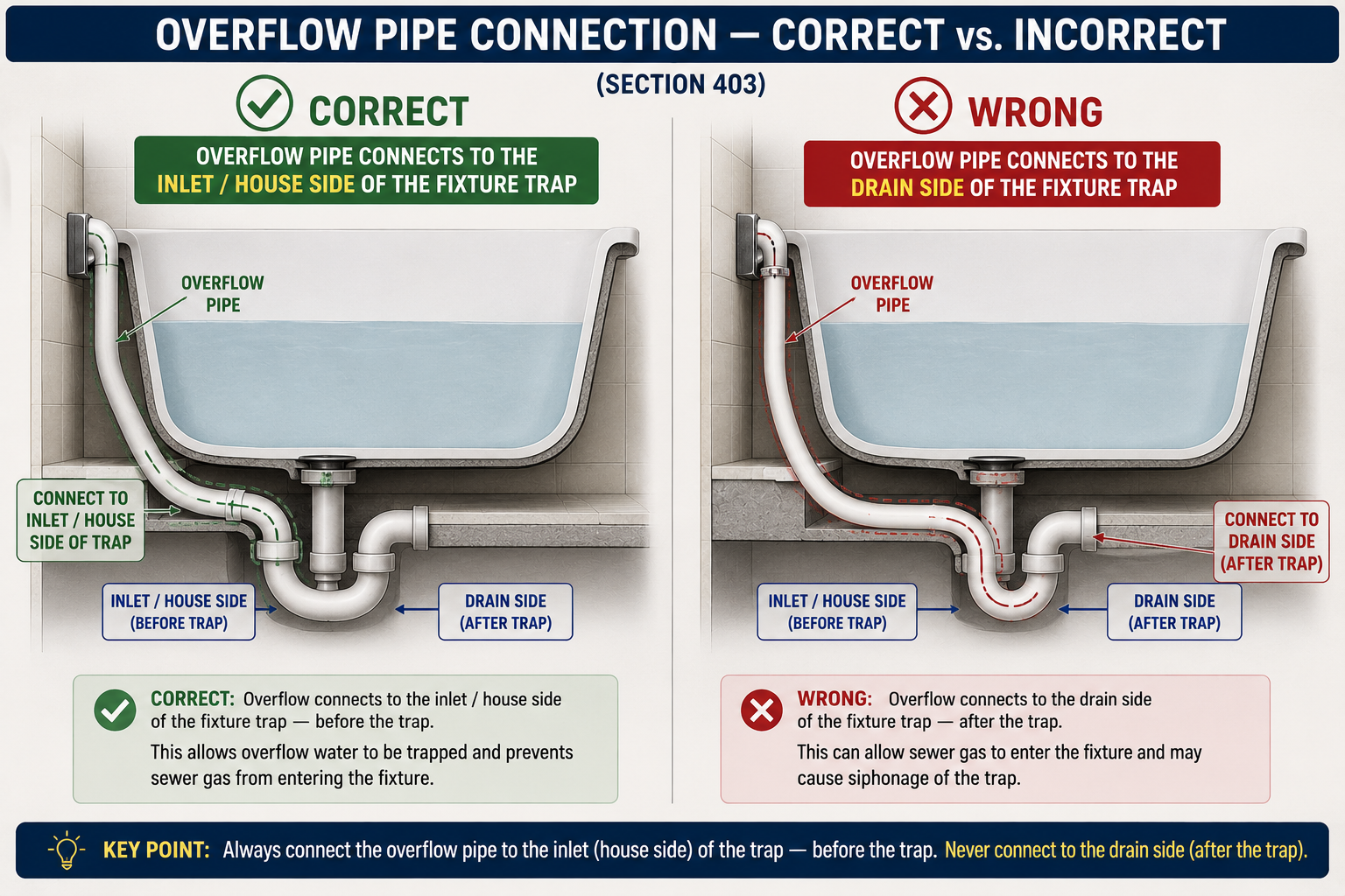
Bathtub overflow pipe connection: correct installation connects to the inlet/house side of the trap (before the trap). Connecting to the drain side after the trap allows sewer gas entry and may cause siphonage — prohibited.
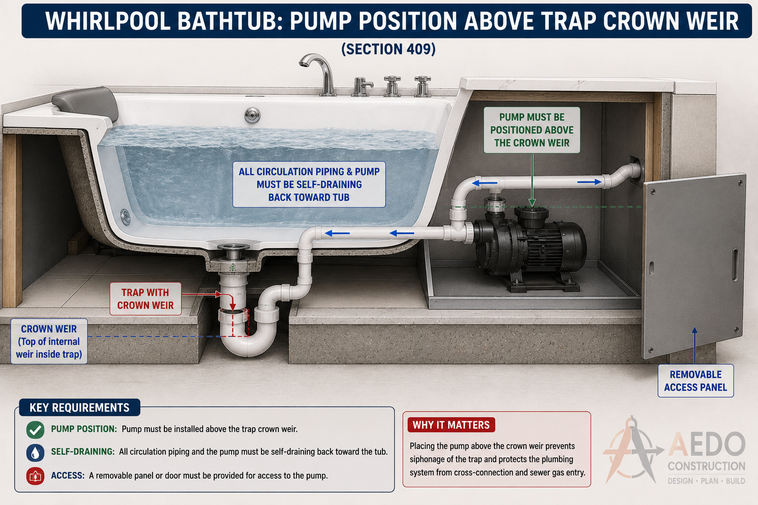
Whirlpool bathtub: the circulation pump must be installed above the trap crown weir, with all piping self-draining back toward the tub. A removable access panel is required for pump maintenance.
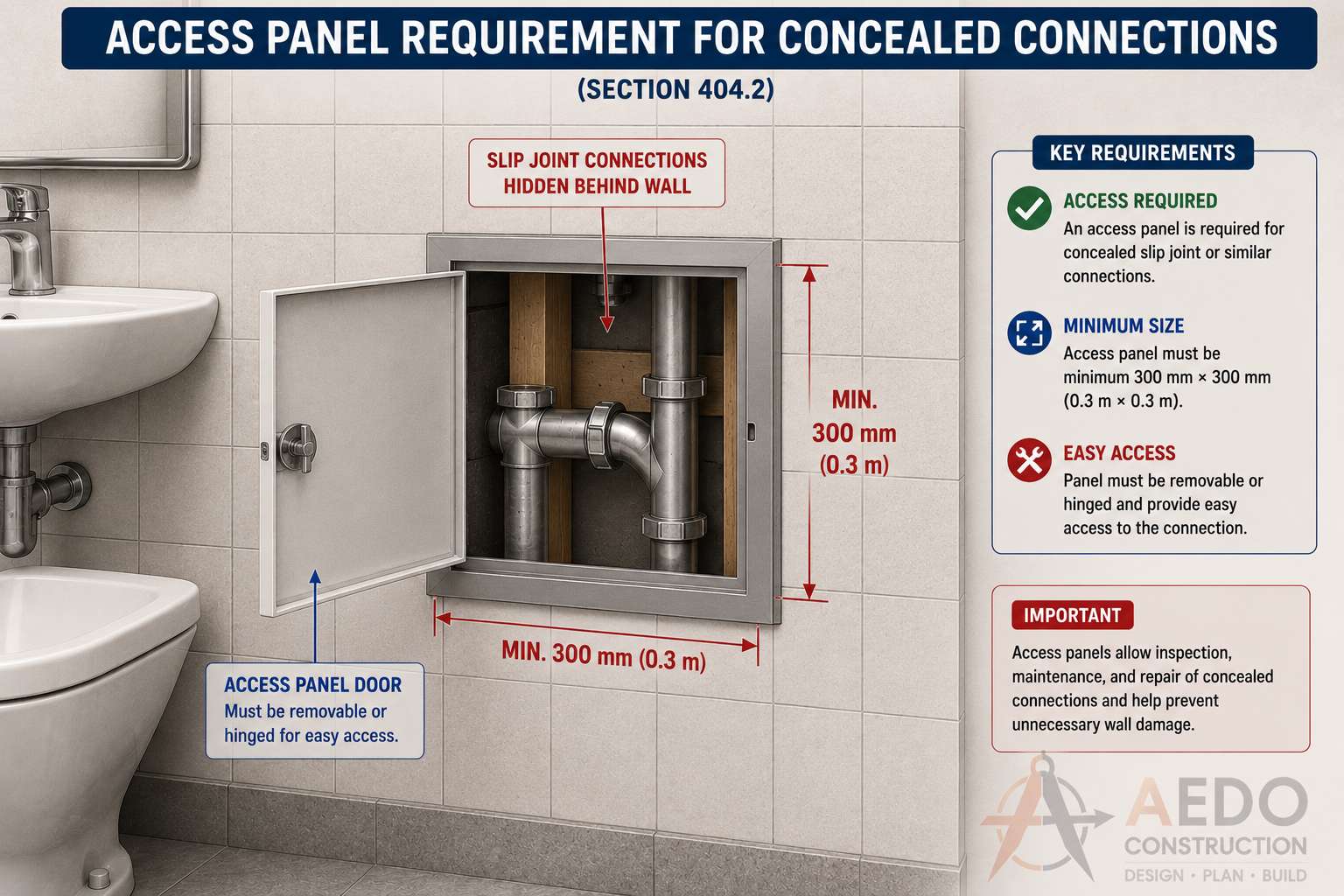
Access panel minimum size: 300mm × 300mm — must be removable or hinged to provide easy access to concealed slip joint connections and trap plumbing behind walls.
Water Closets (WC)
Material, flushing, and drain connection requirements
| Requirement | Specification | Notes |
|---|---|---|
| Minimum drain size | 100 mm (4") | No WC shall connect to a smaller pipe |
| Trap seal depth | 50–100 mm | Integral trap in WC bowl |
| Flush water volume | Maximum 6 liters per flush | Water conservation requirement |
| Flush tank water supply inlet | Must terminate above flood level rim | Anti-siphon ballcock or fill valve required |
| Prohibited design | S-trap or offset siphon bowls | Self-siphoning destroys trap seal |
| Seat | Smooth, non-absorbent, open-front type for public use | Open-front seats required in public toilet rooms |
| Floor-mounted WC bolts | Stainless or brass closet bolts — minimum 2 bolts | With cap covers; properly sealed at floor |
Water Closet Compliance Checker
Enter WC specifications to verify compliance with §408.
WC installation comparison: floor-mounted (left) uses corrosion-resistant expansion bolts with wastewater drain connection; wall-hung (right) uses embedded metal chair bracket. In both cases, the drain pipe carries no structural load.
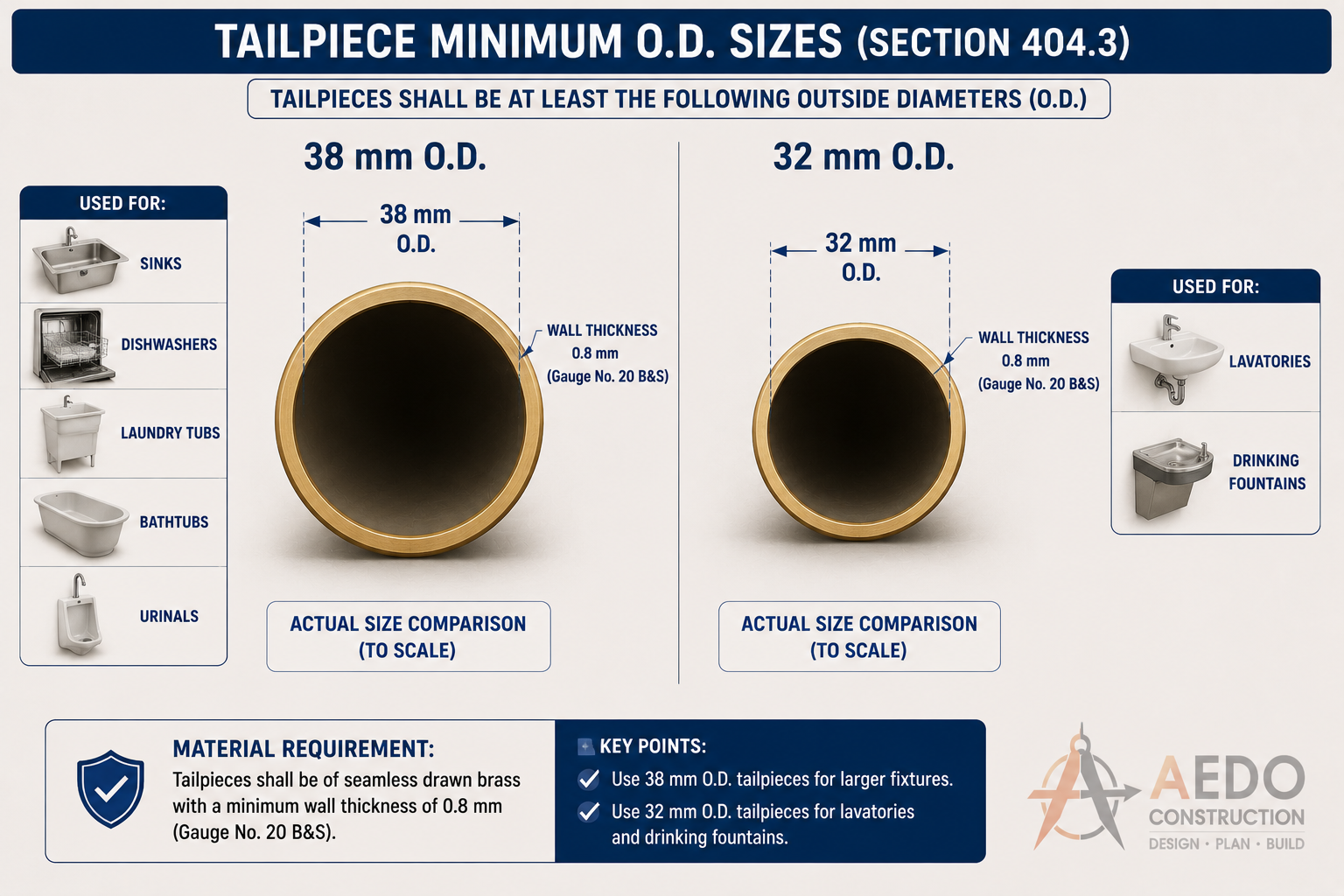
Minimum tailpiece O.D. requirements: 38mm O.D. for sinks, dishwashers, laundry tubs, bathtubs, and urinals; 32mm O.D. for lavatories and drinking fountains. Material: seamless drawn brass, minimum 0.8mm wall thickness (Gauge No. 20 B&S).
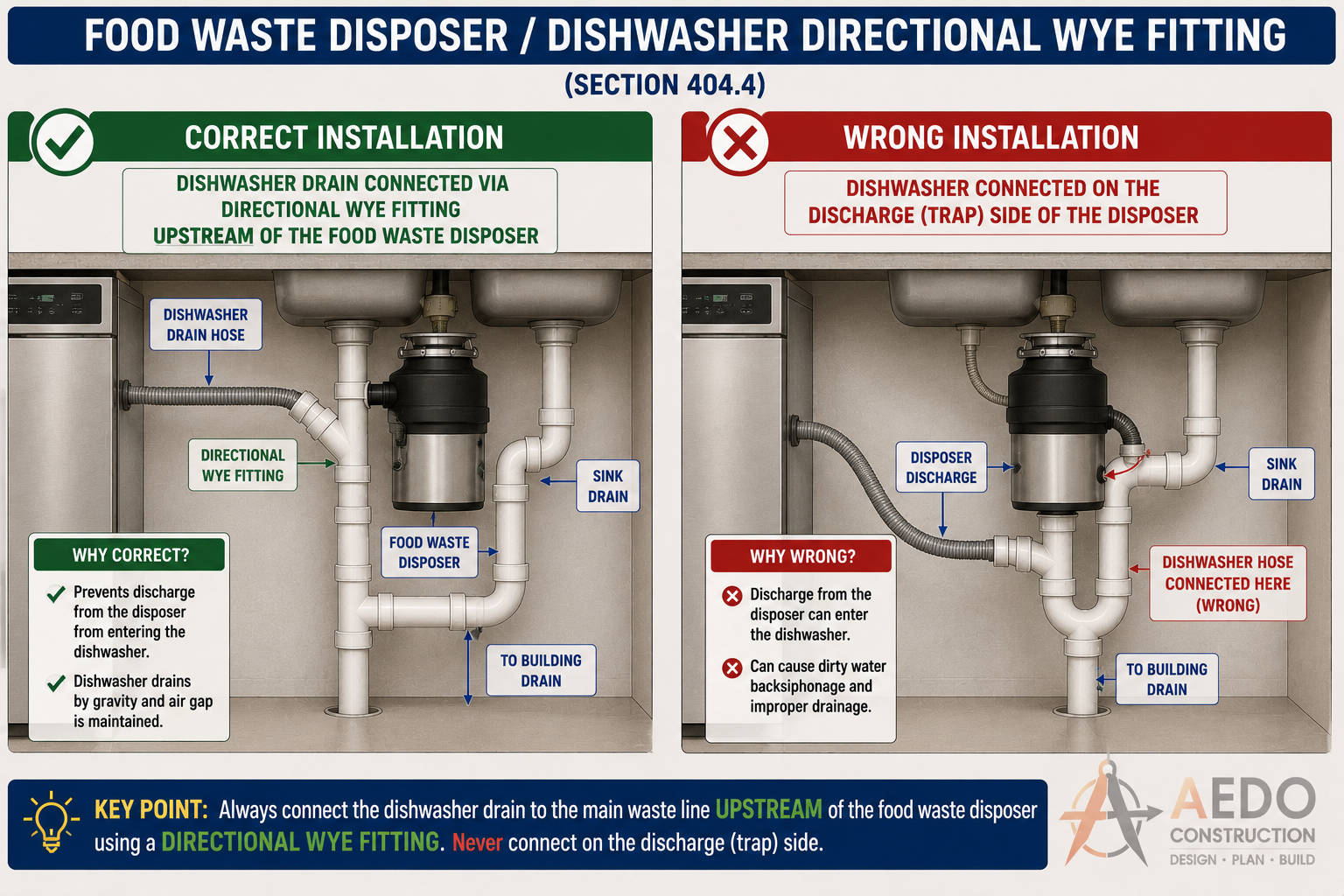
Dishwasher drain connection: connect upstream of the food waste disposer via a directional wye fitting — never on the discharge side of the disposer. Incorrect connection allows disposer discharge to back-flow into the dishwasher.
Water Closet Connection
How the WC connects to the drain system
The water closet outlet (horn) shall connect to the building drainage system through:
A closet (toilet) flange of matching material, permanently bonded to the drain pipe — extends to finished floor level.
A 90° closet bend (short 90° turned 90°) connects the vertical stack or horizontal branch to the flange. Must be 100mm minimum.
Provides a watertight seal between the WC horn and flange. Replace whenever WC is removed.
Urinal Waste Connections
Trap and drain requirements for urinals
| Requirement | Specification |
|---|---|
| Trap seal depth (minimum) | 50 mm |
| Minimum waste connection | 50 mm (2") |
| Trap type | Integral trap preferred; separate P-trap acceptable |
| Flush valve type | Diaphragm or piston-type — no back-siphonage |
| Waterless urinals | Require approved cartridge-type insert for trap seal |
| Urinal flush volume | Maximum 3.8 liters per flush (water conservation) |
Urinal Compliance Checker
Enter urinal specifications to verify compliance with §410.
Minimum Number of Required Plumbing Fixtures
Table 4-1 — Required fixtures by occupancy classification
Note: "M" = Male occupants, "F" = Female occupants. Where occupancy is mixed but proportions are unknown, assume 50/50 split. All counts are minimums — local building code may require more.
Minimum Fixture Calculator
Pick an occupancy and enter the design population. Counts are rounded up per code.
Residential Occupancies
| Occupancy | Water Closets | Lavatories | Bathtub / Shower | Kitchen Sink | Laundry Tub |
|---|---|---|---|---|---|
| Single-family dwelling | 1 per unit | 1 per unit | 1 per unit | 1 per unit | 1 per unit |
| Multi-family dwelling(apartment, condo) | 1 per unit | 1 per unit | 1 per unit | 1 per unit | 1 per building |
| Dormitory / Boarding House(shared facilities) | 1 per 8 persons | 1 per 8 persons | 1 per 8 persons | 1 per floor | 1 per floor |
| Hotel / Motel(private baths) | 1 per room | 1 per room | 1 per room | – | – |
Assembly Occupancies
| Occupancy | WC (Male) | WC (Female) | Urinals (Male) | Lavatories | Drinking Fountain |
|---|---|---|---|---|---|
| Theater, Auditorium, Cinema(seats ≤ 500) | 1 per 500 M | 1 per 150 F | 1 per 150 M | 1 per 500 | 1 per 500 |
| Church, Hall, Convention | 1 per 300 M | 1 per 150 F | 1 per 150 M | 1 per 300 | 1 per 500 |
| Coliseum, Stadium, Arena | 1 per 300 M | 1 per 150 F | 1 per 120 M | 1 per 400 | 1 per 500 |
| Restaurant, Café, Food Court(customers) | 1 per 50 M | 1 per 50 F | 1 per 50 M | 1 per 75 | – |
Business / Educational Occupancies
| Occupancy | WC (Male) | WC (Female) | Urinals (Male) | Lavatories | Drinking Fountain |
|---|---|---|---|---|---|
| Office Building | 1 per 25 M | 1 per 25 F | 1 per 50 M | 1 per 40 | 1 per 75 |
| Elementary / High School(students) | 1 per 30 M | 1 per 25 F | 1 per 35 M | 1 per 40 | 1 per 100 |
| College / University | 1 per 40 M | 1 per 30 F | 1 per 40 M | 1 per 50 | 1 per 100 |
| Hospital / Health Care(patient areas) | 1 per 8 beds M | 1 per 8 beds F | 1 per ward | 1 per bed | 1 per ward |
Industrial / Mercantile Occupancies
| Occupancy | WC (Male) | WC (Female) | Urinals (Male) | Lavatories | Drinking Fountain |
|---|---|---|---|---|---|
| Factory / Industrial Plant(1–100 workers) | 1 per 10 M | 1 per 10 F | 1 per 10 M | 1 per 10 | 1 per 75 |
| Factory / Industrial Plant(101–200 workers) | 1 per 15 M | 1 per 15 F | 1 per 15 M | 1 per 15 | 1 per 75 |
| Mercantile / Retail Store(employees) | 1 per 25 M | 1 per 25 F | 1 per 25 M | 1 per 40 | 1 per 75 |
| Parking Structure | 1 per 500 M | 1 per 500 F | 1 per 500 M | 1 per 500 | – |
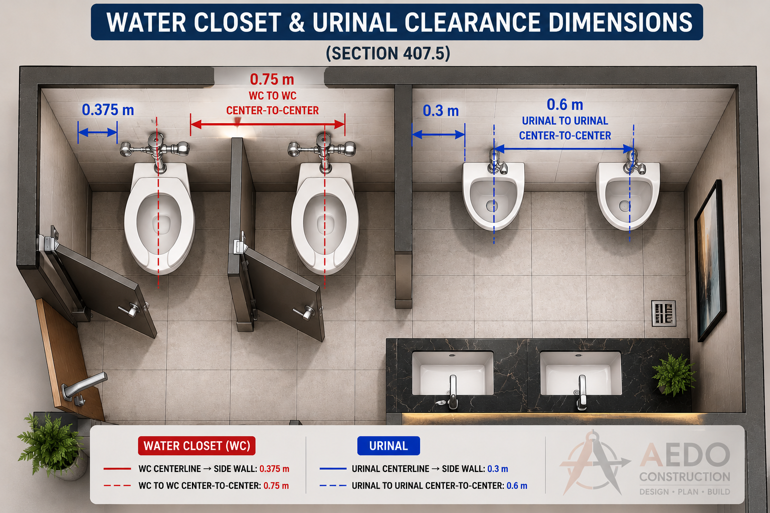
Public toilet room layout showing required clearance dimensions: WC centerline to side wall minimum 0.375m; WC center-to-center minimum 0.75m; urinal centerline to side wall minimum 0.3m; urinal center-to-center minimum 0.6m.