Water Supply & Distribution
Chapter 6 governs the entire potable water supply system — from the utility connection at the street to every faucet, shower, and flush valve inside the building. Core requirements include cross-connection control (preventing contamination of the potable supply), pipe sizing by fixture-unit demand, supply pressure maintained between 103–551 kPa, and a pressure-reducing valve where the upper limit is exceeded.
Water Required
Potable water supply is mandatory for all occupied buildings
Every building intended for human occupancy shall be provided with an adequate supply of pure, potable water. The water supply shall:
Meet Philippine National Standards for Drinking Water (PNSDW) — safe for human consumption, cooking, and personal hygiene.
Adequate static and residual pressure to supply all fixtures simultaneously under peak demand.
Sufficient flow rate to serve all fixtures at minimum design flow rates (see §605–506).
Where utility supply is intermittent, an approved storage tank with minimum 1-day storage shall be provided.
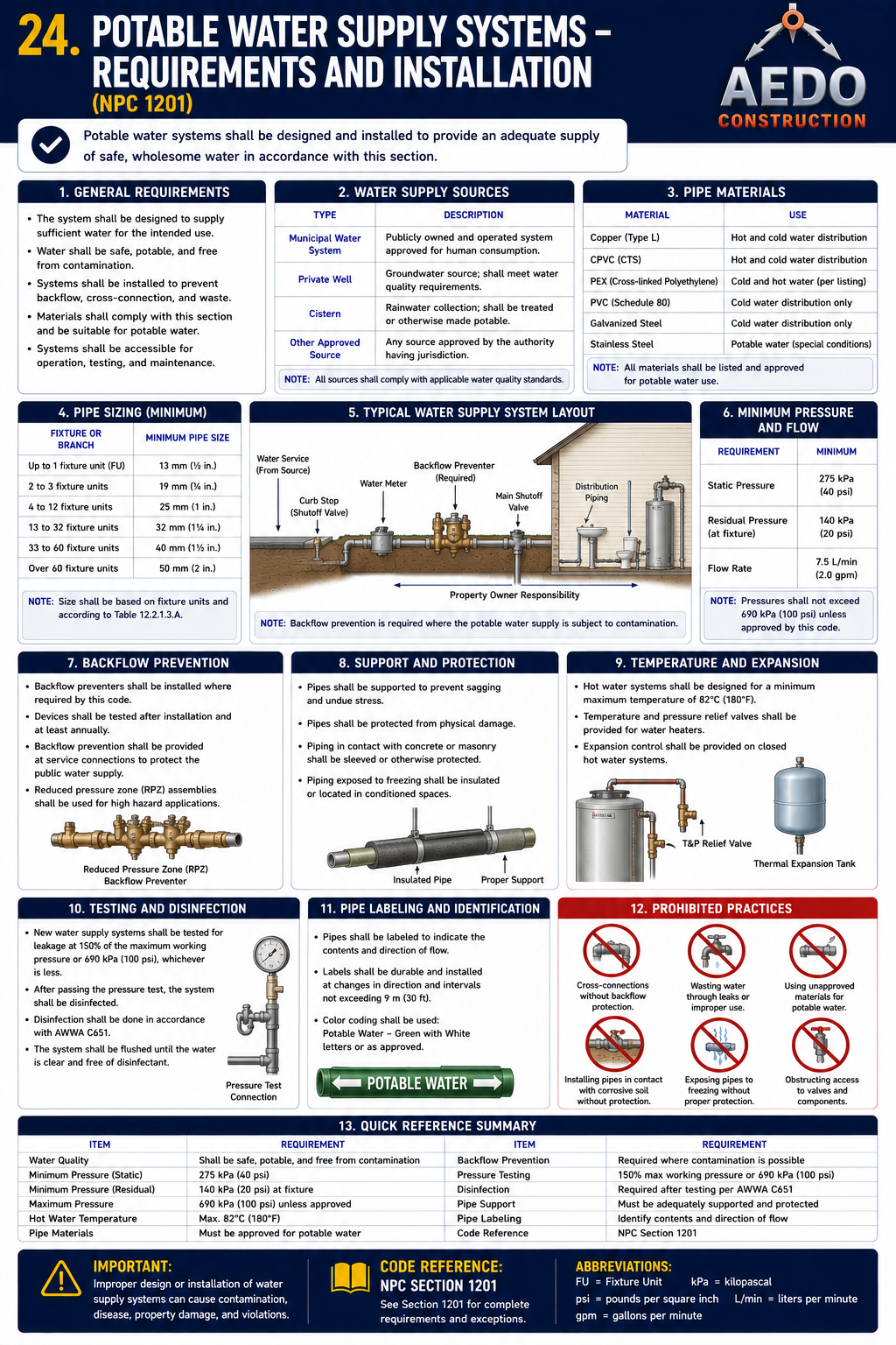
Potable water supply system — requirements & installation. Every occupied building gets an adequate supply of pure, potable water through approved materials, protected from cross-connection by air gaps and backflow devices, sized by water-supply fixture units (WSFU), and maintained at adequate residual pressure (boosted by pump/pressure-tank or elevated tank where utility pressure is insufficient). (NPC §600)
Existing Water Service Pipe
When existing supply pipes must be replaced or upsized
Where an existing building's water service pipe is to be extended or new fixtures added, the plumber shall evaluate whether the existing service pipe is adequate. A new or enlarged service pipe is required when:
- The calculated fixture-unit demand exceeds the capacity of the existing service pipe size (per Table 6-2)
- The available pressure at the meter drops below the minimum required pressure at the critical (highest and farthest) fixture
- The existing pipe shows evidence of scale, corrosion, or flow restriction reducing effective diameter
- The building use changes to a higher-demand occupancy
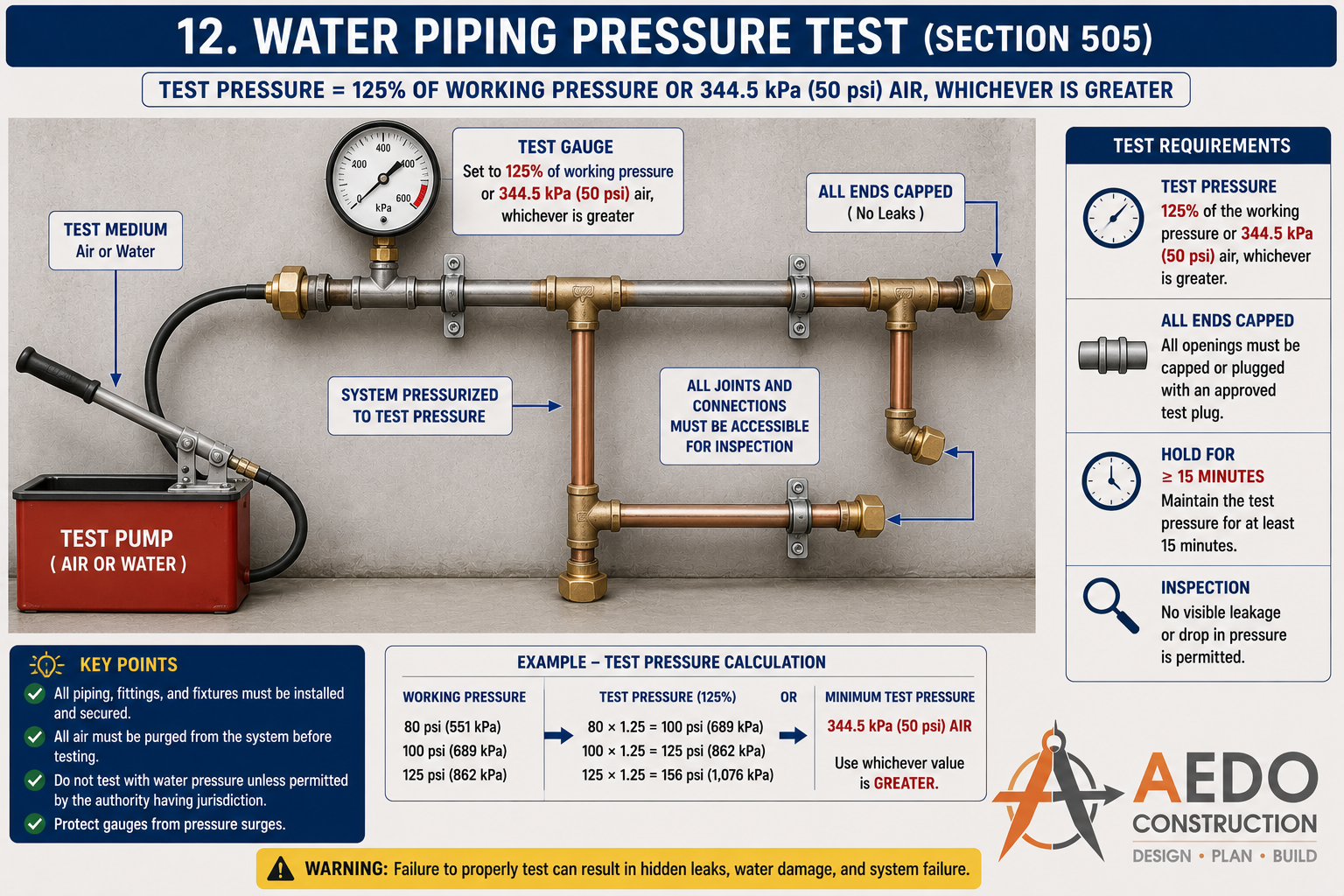
Water piping pressure test: test pressure = 125% of working pressure or 344.5 kPa (50 psi) air — whichever is greater. All ends capped, all joints visible, hold for minimum 15 minutes. No visible leakage or pressure drop permitted.
Connection to Potable Water System
Rules for connecting fixtures and equipment to the supply
| Rule | Requirement |
|---|---|
| Submerged inlets prohibited | No supply pipe or outlet shall terminate below the flood level rim of a fixture — prevents back-siphonage contamination |
| No direct connection to drainage | Supply pipes shall never be directly connected to any drain, soil, or waste pipe |
| No connection to non-potable systems | Irrigation, fire sprinkler (if chemically treated), and industrial process water lines must remain physically separate |
| Approved fittings only | All connections to potable supply use PNS/ASTM-approved fittings — no improvised connections |
| Identification of non-potable pipes | Non-potable piping (recycled, grey-water) shall be identified by color or labeling — cannot appear interchangeable with potable supply |
Potable Water Connection Rules
Select a connection scenario to check if it is permitted under §603.
Protection of Potable Water — Cross-Connection Control
Preventing contamination of the drinking water supply
Required Air Gap Dimensions (Table 6-1)
| Supply Pipe Effective Opening | Not Affected by Side Walls | Affected by Side Walls |
|---|---|---|
| ≤ 13 mm | 25 mm | 38 mm |
| ≤ 19 mm | 38 mm | 57 mm |
| ≤ 25 mm | 51 mm | 76 mm |
| > 25 mm | 2× diameter | 3× diameter |
Air Gap Calculator
Enter supply pipe opening diameter and wall proximity to find the minimum required air gap per §604.
Backflow Prevention Devices
Where an air gap is not practicable, an approved backflow preventer shall be installed:
| Device | Protection Level | Typical Applications |
|---|---|---|
| Air Gap (physical separation) | Highest — absolute | All tanks, cisterns, supply to fixtures |
| Reduced-Pressure Backflow Preventer (RPBP) | High — for toxic hazards | Chemical feed, boiler makeup, irrigation |
| Double Check Valve Assembly (DCVA) | Medium — non-toxic hazards | Fire sprinklers, non-drinking water loops |
| Atmospheric Vacuum Breaker (AVB) | Backflow only (not pressure) | Hose bibbs, flush valve supplies |
| Pressure Vacuum Breaker (PVB) | Back-siphonage only | Irrigation systems, laboratory sinks |
Backflow Device Selector
Describe the hazard and application to find the appropriate backflow prevention device.
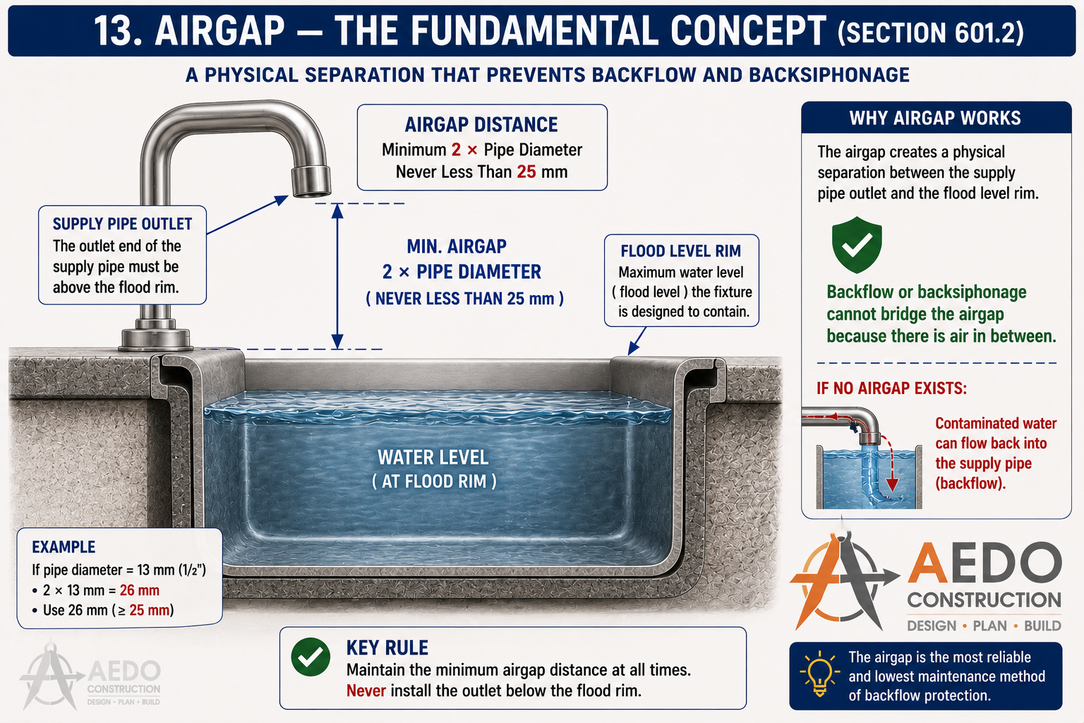
Air gap — the fundamental backflow prevention concept: supply pipe outlet must be above the flood level rim. Minimum air gap per Table 6-1 ranges from 25mm (small openings, unaffected by walls) up to 3× pipe diameter for openings over 25mm near walls. A submerged inlet with no air gap allows contaminated water to back-siphon into the supply.
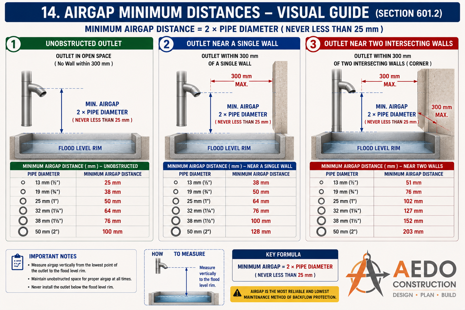
Air gap minimum distances for three outlet conditions: unobstructed (2× pipe dia., min 25mm), near a single wall within 300mm (increased), and near two intersecting walls (further increased). Always measure vertically from the lowest point of the outlet to the flood level rim.
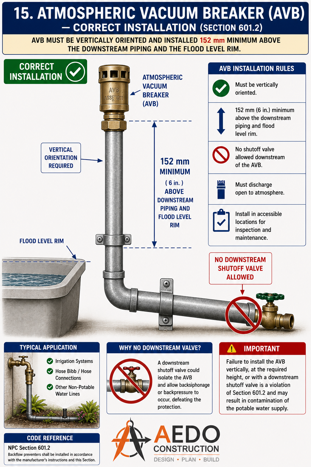
Atmospheric Vacuum Breaker (AVB): must be vertically oriented and installed minimum 152mm above downstream piping and flood level rim. No downstream shutoff valve allowed — a downstream valve would defeat the protection by allowing back-pressure to build.
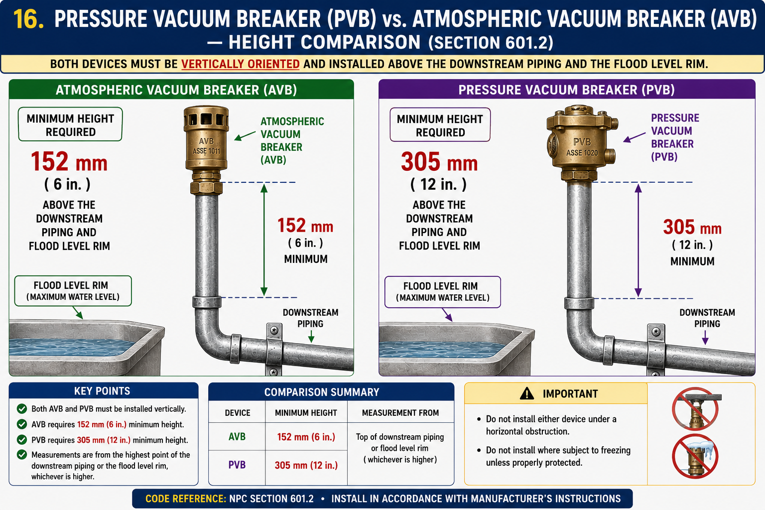
Height comparison: AVB requires minimum 152mm (6 in.) above downstream piping and flood level rim; PVB requires minimum 305mm (12 in.). Both must be vertically oriented. PVB offers higher protection level suitable for irrigation systems.
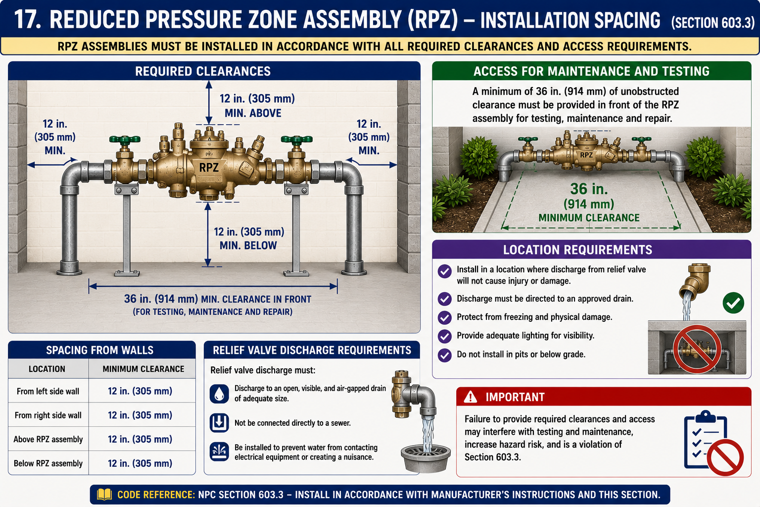
Reduced Pressure Zone (RPZ) assembly clearances: 305mm above, below, and from side walls; minimum 914mm clearance in front for testing and maintenance. Relief valve discharge must drain to an open, air-gapped drain — never directly to a sewer.
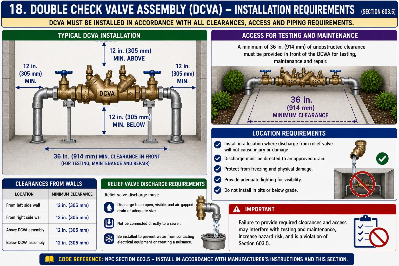
Double Check Valve Assembly (DCVA): same 305mm side/above/below clearances as RPZ, 914mm minimum front clearance. Used for medium-hazard non-toxic applications such as fire sprinkler systems and non-drinking water loops.
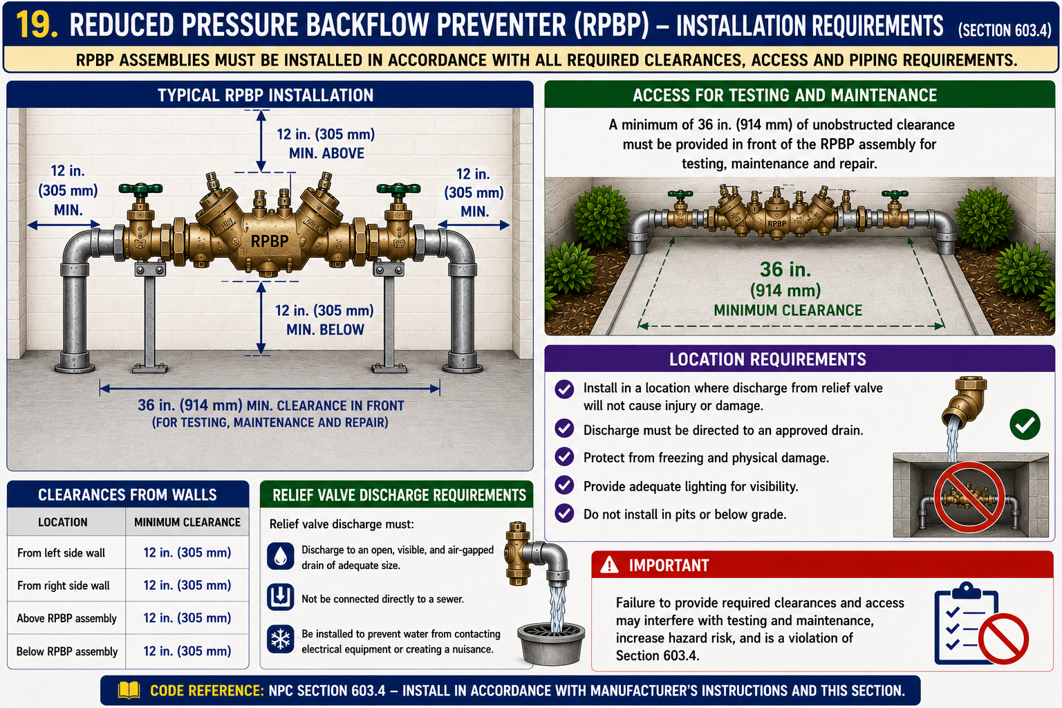
Reduced Pressure Backflow Preventer (RPBP): highest mechanical protection for high-hazard toxic applications (chemical feed, boiler makeup, irrigation with fertilizers). Install with isolation valves on both sides, strainer upstream, and test cocks accessible. Relief valve discharge must not connect to sewer.
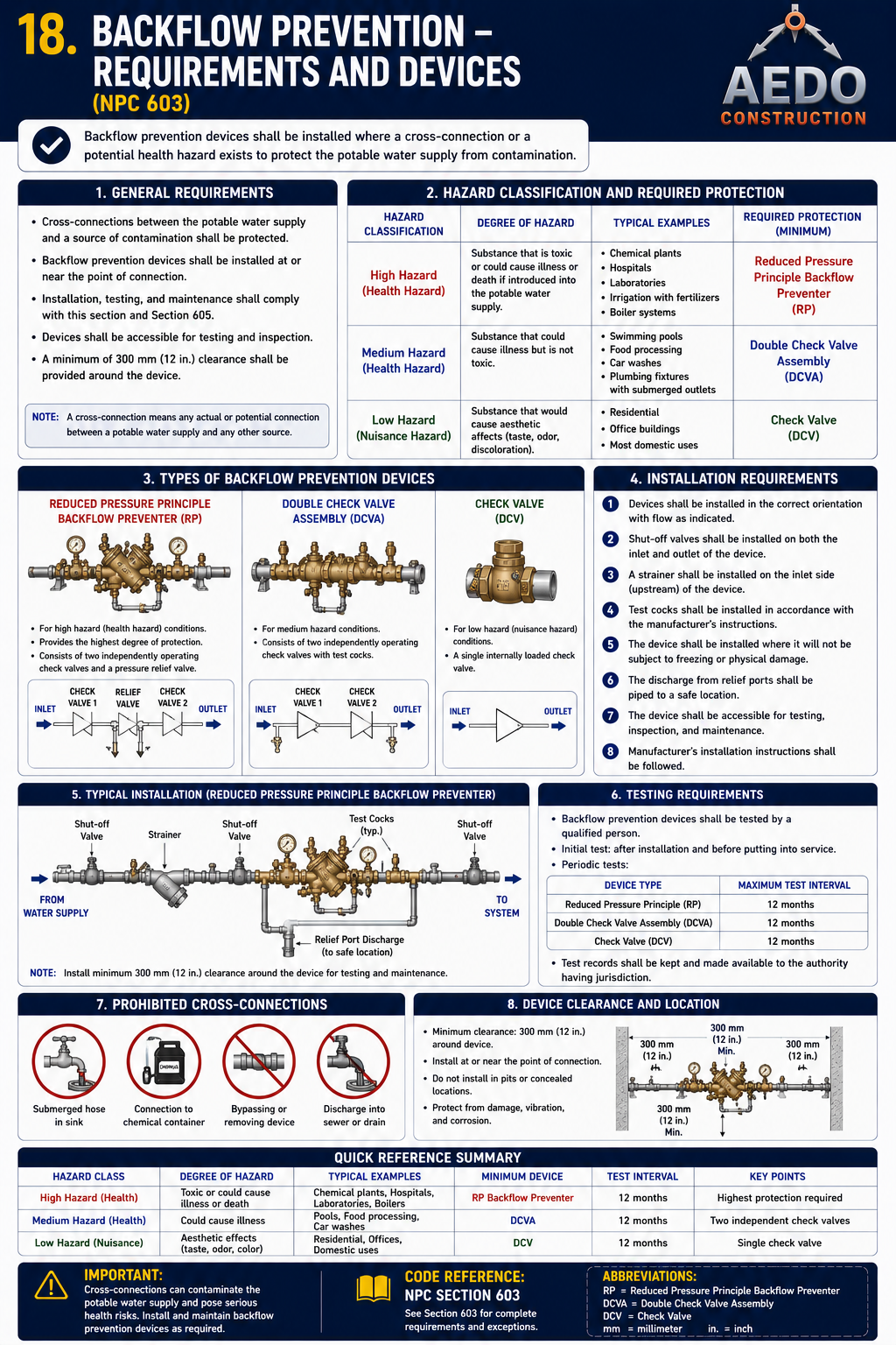
Backflow prevention — full quick reference. Hazard classification (high/medium/low) and the required protection for each, the main device types (RP, DCVA, check valve), installation and clearance requirements, periodic testing intervals, prohibited cross-connections, and a hazard-to-device summary table.
Water Supply Fixture Unit (WSFU) Values
Table 6-5 — Equivalent Water Supply Fixture Units (includes combined hot & cold water demands)
| # | Fixture | WSFU — Private Use | WSFU — Public Use |
|---|---|---|---|
| 1 | Bar Sink | 1 | 2 |
| 2 | Bathtub (with or without shower over) | 2 | 4 |
| 3 | Bidet | 2 | 4 |
| 4 | Dental Unit or Cuspidor | — | 1 |
| 5 | Drinking Fountain (each faucet) | 1 | 2 |
| 6 | Hose Bibb / Sill Cock (standard type) | 3 | 5 |
| 7 | Laundry Tub / Clothes Washer (each pair of faucets) | 2 | 4 |
| 8 | Lavatory | 1 | 2 |
| 9 | Lavatory (dental) | 1 | 1 |
| 10 | Lawn Sprinkler (standard type, each head) | 1 | — |
| 11 | Mobile Home (each) | 6 | 6 |
| 12 | Shower (each head) | 2 | 4 |
| 13 | Sink (bar) | 1 | 2 |
| 14 | Sink (flushing rim, clinic) | — | 10 |
| 15 | Sink or Dishwasher | 2 | 4 |
| 16 | Sink (wash-up, circular spray) | — | 4 |
| 17 | Sink (wash-up, each set of faucets) | — | 2 |
| 18 | Urinal (flush tank) | — | 3 |
| 19 | Urinal (pedestal or similar type) | — | 10 |
| 20 | Urinal (stall) | — | 5 |
| 21 | Urinal (wall) | — | 5 |
| 22 | Water Closet (flush tank) | 3 | 5 |
| 23 | Water Closet (economical flush) | 2.5 | 4 |
| 24 | Water Closet (flushometer-tank) | 3 | 5 |
| 25 | Water Closet (flushometer valve) | * | * |
* Flushometer valves & unlisted outlets: water-supply outlets for fixtures not listed above shall be computed at their maximum demand, but in no case less than the values below (Private / Public):
a. 9.5 mm outlet — 1 / 2 b. 13 mm outlet — 2 / 4 c. 19 mm outlet — 3 / 6 d. 25 mm outlet — 6 / 10
See §609.9 for the method of sizing flushometer-valve installations using Table 6-6.
WSFU Demand Counter
Add fixtures to tally total Water Supply Fixture Units per NPC Table 6-5. Switch Private/Public Use to match your occupancy — the WSFU value updates automatically.
Water Distribution Pipe Sizing
NPC Tables 6-6.1 – 6-6.3 — pipe & meter sizing by fixture-unit load, supply pressure, and run length
For quick planning purposes, the simplified reference below summarizes typical minimum branch sizes against approximate WSFU ranges (mid-range 46–60 psi assumptions, short runs). It is a planning aid only — final sizing must use Tables 6-6.1–6-6.3 with your project's actual supply pressure and pipe-run lengths.
| Nominal Pipe Size | Approx. WSFU (branch, short run) | Approx. WSFU (main/meter, short run) | Approx Flow (L/min) |
|---|---|---|---|
| 13 mm (½") | 1–3 | – | ~7.6 |
| 19 mm (¾") | 4–6 | 6–14 | ~15 |
| 25 mm (1") | 7–17 | 15–24 | ~23 |
| 32 mm (1¼") | 18–30 | 25–39 | ~27 |
| 38 mm (1½") | 31–60 | 40–78 | ~38 |
| 51 mm (2") | 61–150 | 79–151 | ~57 |
| 64 mm (2½") | 151–300 | 152–370 | ~76 |
| 76 mm (3") + | 300+ | 370+ | ~114+ |
Approximate WSFU bands derived from the lower-load (longer permissible run) columns of Tables 6-6.1–6-6.3 for orientation only — actual minimum size for any specific run shrinks as developed length increases. Always verify against the governing table for your supply-pressure range.
Water Supply Pipe Sizer (Preliminary Estimate)
Enter total WSFU demand (from the §605 counter) and your supply-pressure range for a preliminary minimum-size estimate. This is a planning aid based on the simplified band table above — confirm the final size against NPC Tables 6-6.1–6-6.3 using your actual developed pipe length.
Hot Water Supply
Temperature limits, safety devices, and heater requirements
Per Chapter 4 §409.7, shower and tub control valves shall be limited to a maximum of 48.88°C at the fixture.
Per §603.3.5, hot water reaching a point protected by a backflow device shall not exceed 43.3°C.
Every water heater shall have a T&P relief valve sized for the heater's BTU/hr input. Discharge pipe terminates near floor — never over electrical equipment.
Where a backflow preventer or PRV creates a closed system, a thermal expansion tank is required on the cold supply to the heater.
| Hot Water Requirement | Specification | Applies To |
|---|---|---|
| Shower / tub control valve (max) | 48.88°C | Per Ch.4 §409.7 |
| Backflow-protected hot water (max) | 43.3°C | Per §603.3.5 |
| T&P relief valve — required | Yes — at heater; relief pipe ≥ heater outlet size | All storage water heaters |
| T&P discharge pipe material | Same as supply pipe; terminate visible, near floor | No cap, no reduction at end |
| Heater location — no confined space | Adequate air supply for combustion (gas heaters) | Gas-fired water heaters |
| Seismic strapping | Required for all storage heaters > 75L capacity | Earth movement zones |
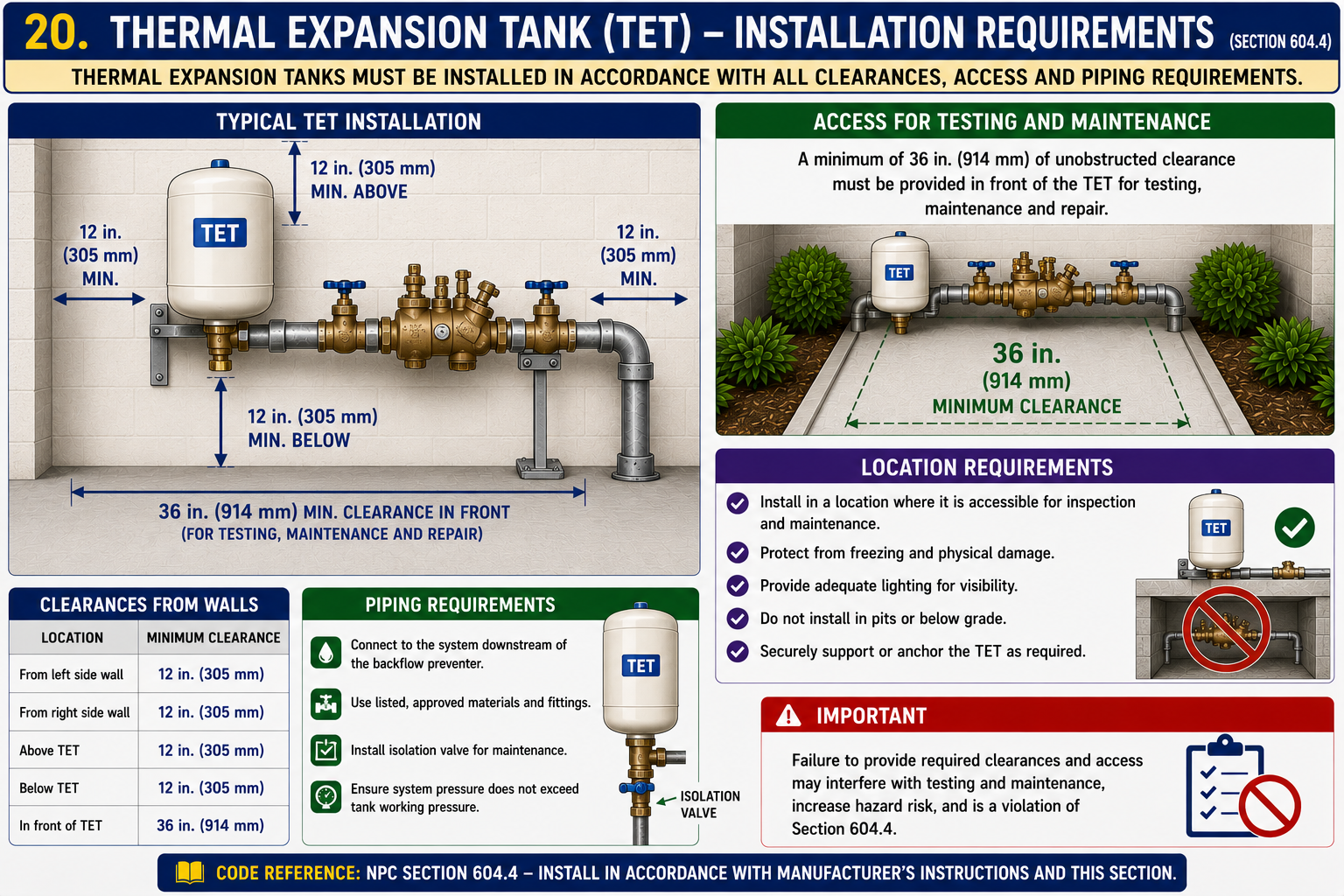
Thermal Expansion Tank (TET): required downstream of a backflow preventer or PRV where a closed system is created. Connect downstream of the backflow preventer, with isolation valve for maintenance. Minimum 305mm clearance on all sides; 914mm in front.
Hot Water Temperature Compliance
Enter hot water temperatures to check compliance with §607 limits.
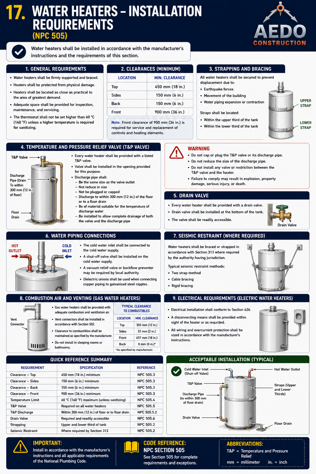
Water heaters — installation requirements. Provide a temperature-and-pressure (T&P) relief valve sized to the heater input, with the discharge piped full-size to within ~150 mm of the floor (no cap or reduction); a drain pan with indirect drain where leakage could cause damage; seismic strapping; full service clearances; and adequate combustion-air supply for gas units. Storage temperature shall not exceed 60 °C. (NPC §600)
Drinking Water
Access to potable drinking water in occupied buildings
- Potable drinking water shall be accessible within 60 meters of travel distance from any occupied work area.
- Drinking fountains are required per §411 minimum fixture table (see Chapter 4). For offices: 1 per 75 persons; for schools: 1 per 100 students.
- Drinking fountain supply shall be connected only to potable water — no grey-water or reclaimed water connections permitted.
- Fountains shall have an angled, non-removable nozzle that delivers water in an arc — the mouth shall not contact the nozzle during drinking (anti-contamination design).
- Minimum pressure at fountain: 138 kPa (20 psi); maximum: 415 kPa (60 psi).
Alternative Water Sources
Rainwater, greywater, and reclaimed water systems
Non-potable water sources may be used for toilet flushing, irrigation, and cooling tower makeup — never for drinking, cooking, or personal hygiene. Requirements:
| Requirement | Specification |
|---|---|
| Physical separation from potable supply | No connection, direct or indirect, between potable and non-potable piping systems |
| Pipe identification | Non-potable pipes must be clearly labeled "NON-POTABLE — DO NOT DRINK" every 1.5m and at each valve, fitting, and outlet |
| Color coding | Purple (lavender) piping or purple tape wrap is the standard color for reclaimed/recycled water |
| Dual-flush toilets | Approved for potable supply connection; water conservation devices encouraged but must still meet §408 flushing requirements |
| Rainwater harvesting | First-flush diverter required; storage tanks must be covered and sealed; overflow drains to storm drain (not sanitary) |
| Cross-connection protection | Potable water makeup to non-potable storage must be through air gap only — never direct connection |
Pressure-Reducing Valve (PRV)
Required when static supply pressure exceeds 551 kPa
| PRV Requirement | Specification |
|---|---|
| Minimum supply pressure | 103 kPa |
| Trigger pressure (install required) | > 551 kPa |
| Relief valve setting (max) | ≤ 1,033 kPa |
| Strainer | Required upstream of PRV — protects the valve seat |
| Isolation valves | Ball valves upstream and downstream for maintenance |
| Pressure gauge | Required on downstream side to verify setting |
| Thermal expansion tank | Required downstream where PRV creates a closed system |
| Bypass | Bypass line with globe valve — for maintenance access without shutting down building |
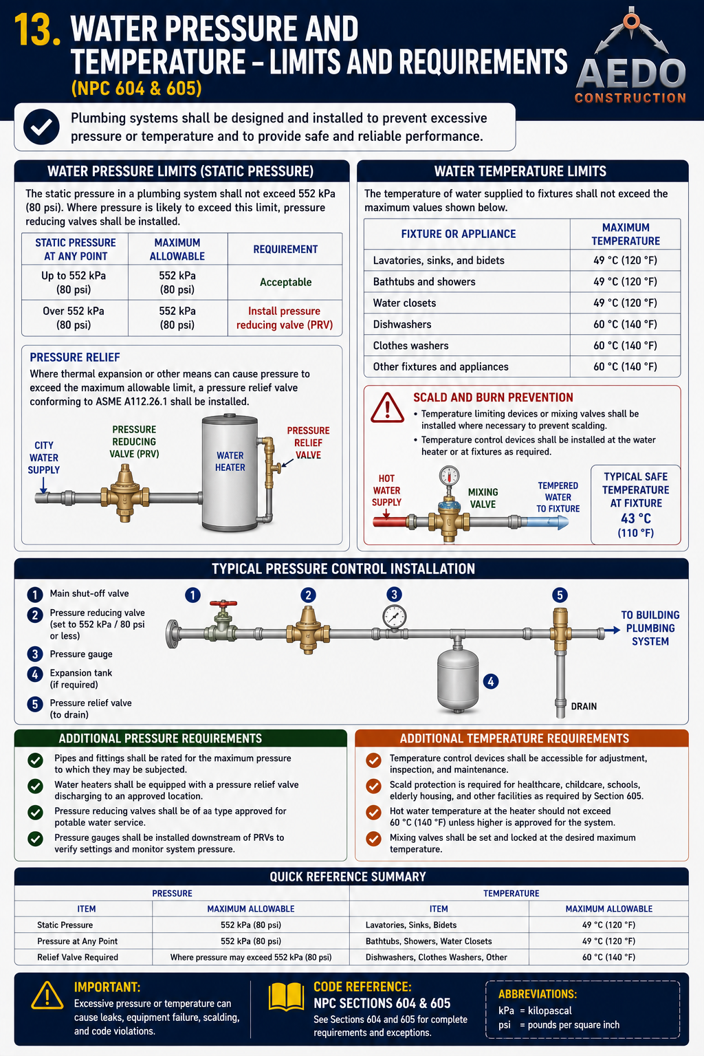
Pressure limits: supply pressure shall be not less than 103 kPa nor more than 551 kPa (§607.1–607.2) — install a PRV where the upper limit is exceeded; relief valves are capped at 1,033 kPa (§607.4). Shower/tub mixing valves are limited to 48.88°C at the fixture (Chapter 4 §409.7), and hot water reaching a backflow-protected outlet is limited to 43.3°C (§603.3.5).
PRV Requirement Checker
Enter the static supply pressure at the building entry point to determine if a Pressure-Reducing Valve is required under §610.
Shut-off Valves
Where isolation valves are required
| Location | Valve Type | Requirement |
|---|---|---|
| At the water service entrance (inside building) | Full-bore ball valve | Main building shutoff — accessible at all times |
| Each floor / zone branch | Ball valve or gate valve | Can isolate a floor without shutting whole building |
| Supply to each water heater | Ball valve on cold supply inlet | Required for heater replacement without building shutoff |
| At each fixture (under-counter) | Angle stop (fixture supply valve) | Required — allows fixture repair without floor shutoff |
| At each flush valve (WC, urinal) | Integral stop on flush valve | Required — screwdriver-adjustable or push-turn type |
| At dishwashers, washing machines | Ball valve on supply hose connection | Required — accessible without moving appliance |
Shutoff Valve Requirements Lookup
Select a location to see the required shutoff valve type and specifications per §611.
Water Hammer Arrestors
Protecting the system from hydraulic shock
Water hammer (hydraulic shock) occurs when a fast-closing valve suddenly stops water flow, creating a pressure spike that can reach 10× the normal working pressure. This can crack pipes, loosen joints, and damage equipment.
| Condition Requiring Arrestor | Recommended Arrestor Size |
|---|---|
| Solenoid-operated valves (dishwashers, washing machines) | Size per ASSE 1010 — based on supply pipe size and flow rate |
| Flush valves (WC, urinal) — especially flush-valve WC at 6 FU demand | Install at end of branch serving flush valves |
| Quick-closing faucets (single-lever ball type) | Recommended at lavatories and sinks on branch ends |
| Long runs (>30m) of supply pipe | Install at end-of-run to absorb pressure waves |
Water Hammer Arrestor Checker
Select the installation scenario to determine if a water hammer arrestor is required per §612.
Water Conservation
Maximum flow rates and water-efficient fixtures
| Fixture / Device | Maximum Flow / Flush Volume | Notes |
|---|---|---|
| Water closet (WC) | 6.0 L per flush | Dual-flush: 3L (liquid) / 6L (solid) encouraged |
| Urinal | 3.8 L per flush | Waterless urinals: approved with cartridge trap |
| Lavatory faucet | 8.3 L/min at 415 kPa | Flow restrictor or aerator required |
| Kitchen sink faucet | 8.3 L/min at 415 kPa | Spray attachments ≤ 9.5 L/min |
| Showerhead | 9.5 L/min at 550 kPa | Flow-limiting device required at each showerhead |
| Metered faucets | 1.9 L per metering cycle | Minimum 10-second flow duration before shutoff |
Water Conservation Compliance Checker
Select the fixture type and enter the measured flow rate or flush volume to check compliance with §613 maximum limits.