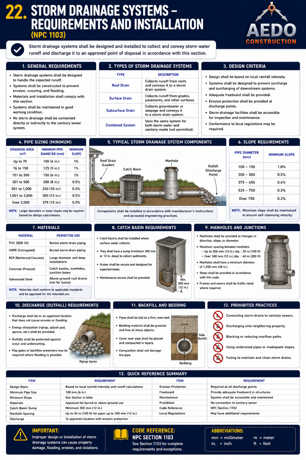
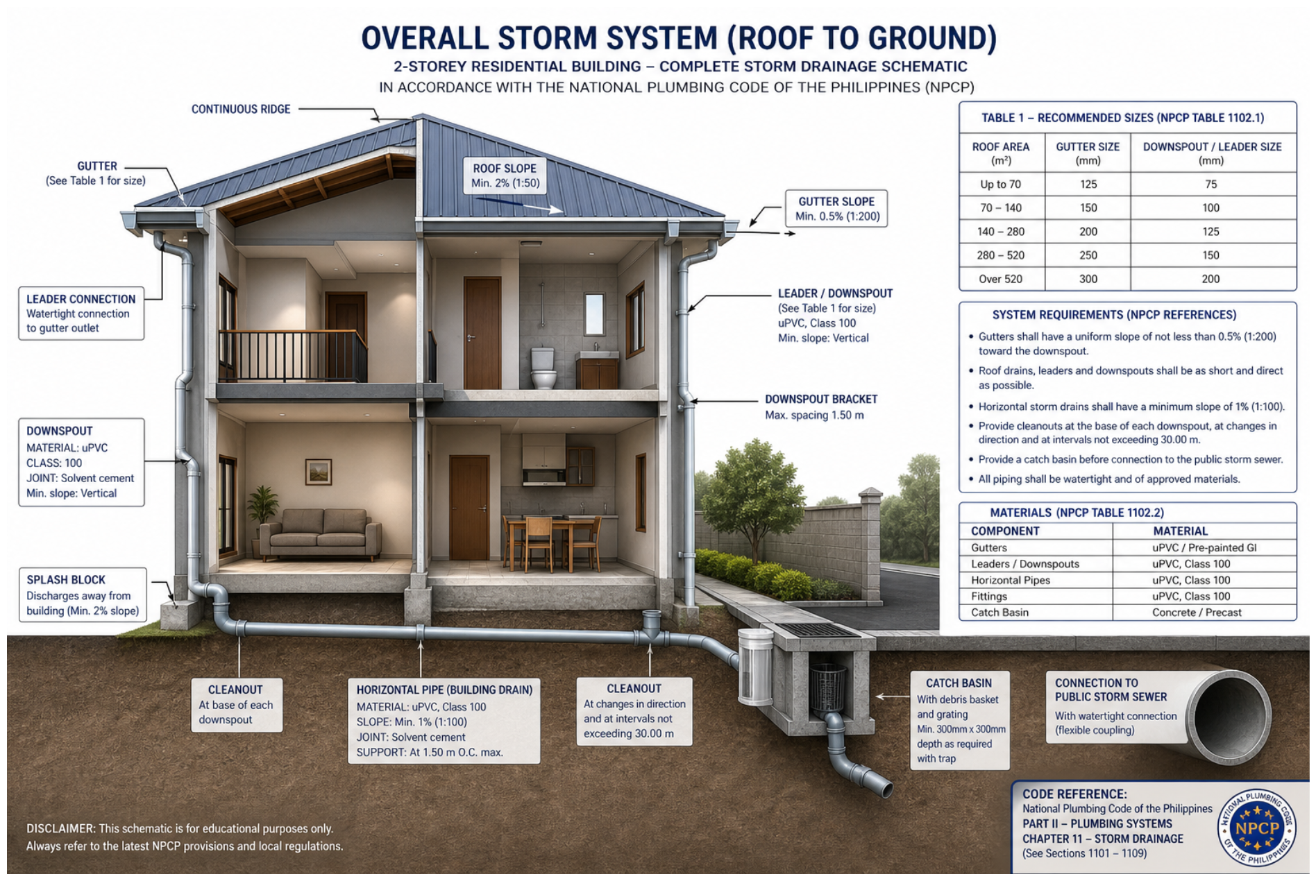
§1101–§1110 · Roof drain sizing, leaders and conductors, area drains, subsoil drainage, sump pumps, and the mandatory separation of storm and sanitary drainage systems — especially critical in typhoon-prone Philippines.
10 SectionsNPC 2000Typhoon SeasonRA 1378
🌧️
Chapter 11 — Storm Drainage
The Philippines receives among the highest rainfall in Southeast Asia — Metro Manila averages 2,000mm annually, with Baguio City receiving up to 5,000mm. Typhoons can bring 200–400mm in a single day. This chapter governs the collection and disposal of stormwater from roofs, paved areas, and below-grade spaces to prevent building damage and flooding. The key mandate: storm and sanitary drainage systems must never be combined.
🚫
Storm drainage shall not be connected to the sanitary drainage system — §1110. These are two separate, permanently distinct systems.
§1101–§1102
Scope & Design Rainfall Rate
ScopeCritical
§1101. Scope. The provisions of this Chapter shall govern the materials, design, and installation of storm drainage systems within the premises of a building or structure.
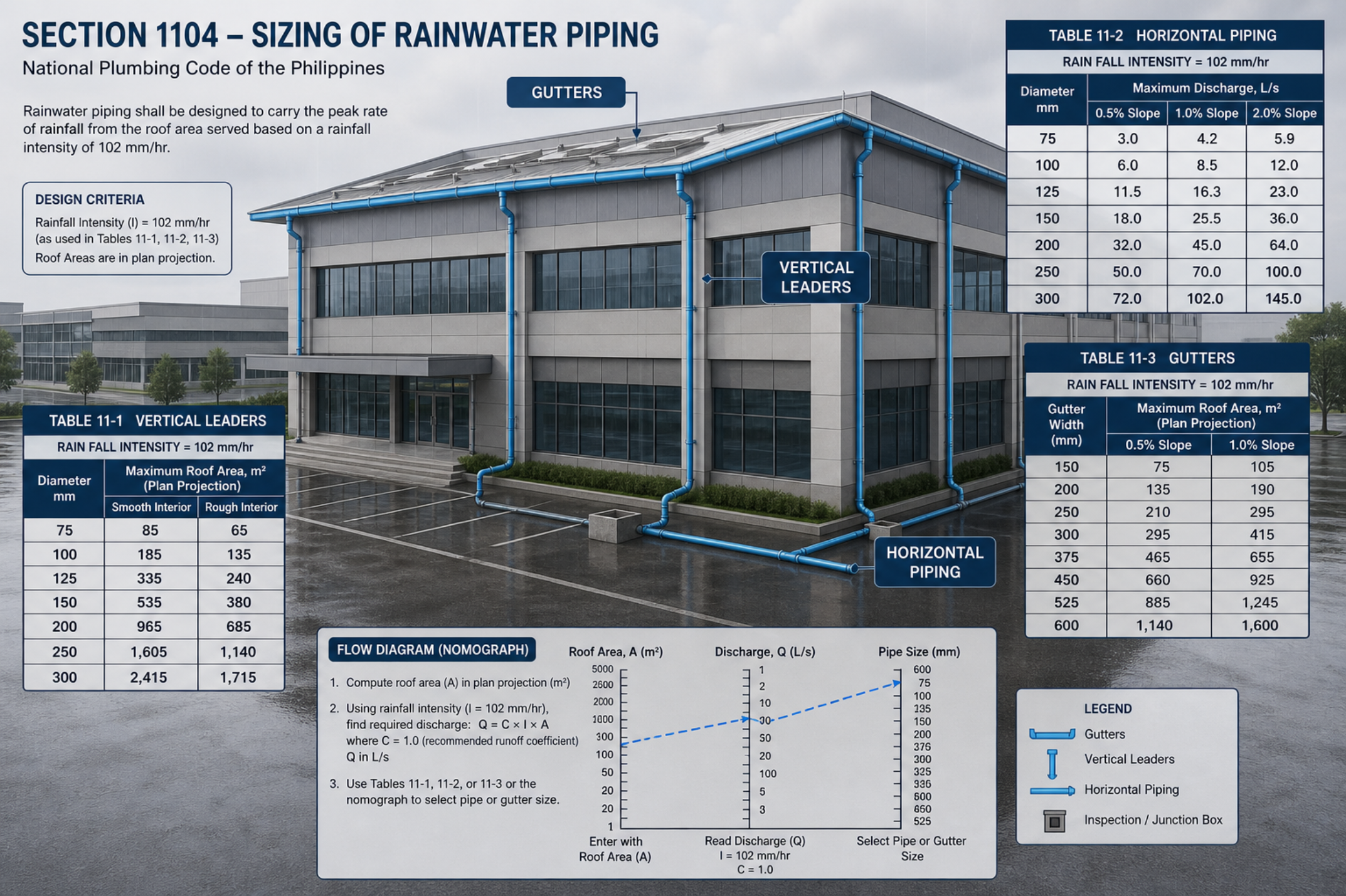
§1102. Rainwater Systems — Materials. This section governs the approved materials for rainwater piping. The Tables in this chapter (11-1, 11-2) use a design rainfall intensity of 102 mm/hour as the worked Metro Manila example — the actual design rate for any project must be based on local rainfall data, not treated as a fixed code minimum.
§1102 covers materials; the 102mm/hr figure that appears throughout this chapter's sizing tables is a Metro Manila design example, not a universal floor value. Always confirm the design rainfall intensity for your specific site against actual local data.
Treating 102mm/hr as a fixed "minimum" is dangerous outside Metro Manila — many Philippine locations experience sustained rainfall well above that figure during typhoons. Undersized systems cause roof ponding, structural overload, building flooding, and mold damage. Always use the rainfall intensity appropriate to the actual project site.
Philippine Practice: Always obtain PAGASA's Rainfall Intensity Duration Frequency (RIDF) data for the specific project location. PAGASA publishes RIDF curves per weather station. Use the 10-year return period for residential buildings, 25-year for commercial/institutional. Submit design rainfall assumptions with the sanitary engineering plans for building permit.
Storm drainage system — requirements & installation. Roof drains, vertical leaders/conductors and horizontal storm drains are sized for a 100-year / 60-minute design storm. Dome (basket) strainers extend ≥102 mm above the roof; flat-deck strainers give ≥2× the conductor area. Provide independent secondary (overflow) drains/scuppers for parapet-enclosed roofs. Storm water shall stay completely separate from the sanitary (excreta) system. When sizing for driving rain, add 50% of one adjacent vertical wall's area (35% for two adjacent walls; 0% for two equal opposite walls) to the roof area. (NPC §1101)
§1103
Roof Drains
DesignSizing
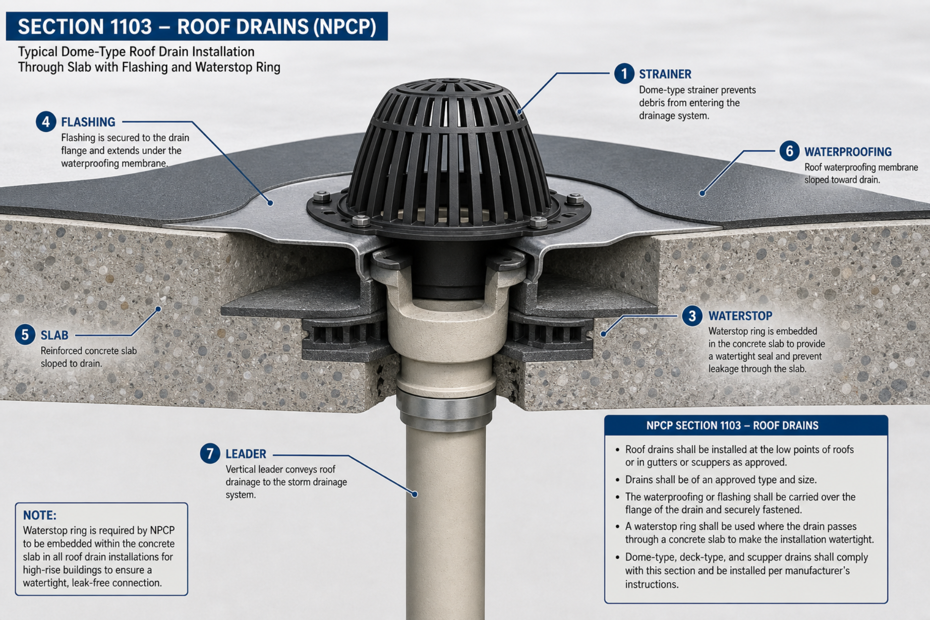
§1103. Rainwater Systems — Roof Drains (Materials & Strainers). This section governs approved roof drain materials and strainer requirements. Detailed siting (lowest points of roof), overflow scupper height, and minimum drain/sump dimensions are project-specific design decisions, not fixed numeric floors stated in this section — confirm exact figures against the design tables in this chapter and sound roofing practice.
Roof drains belong at the lowest roof points, sized per the chapter's sizing tables for the project's design rainfall intensity. For enclosed (parapet) roofs, overflow scuppers are required as an emergency overflow in case primary drains clog — confirm exact heights/dimensions with the Administrative Authority rather than treating any single figure as a universal code minimum.
A clogged roof drain on an enclosed (parapet) roof is catastrophic — ponded water creates structural loads the roof was not designed for. At 100mm depth, a 100m² roof holds 10,000 kg of water. Overflow scuppers are a life-safety feature, not optional.
[CH11-DIAGRAM-A] — Roof drain cross-section with overflow scupper detail
§1104–§1105
Leaders, Conductors & Horizontal Branches
SizingDesign
§1104. Sizing of Rainwater Piping. Leaders and horizontal rainwater piping shall be sized per the tables in this chapter (Tables 11-1, 11-2) on the basis of the roof drainage area served and the project's design rainfall intensity — not a fixed nominal diameter. Storm drainage must remain a system separate from the sanitary drainage system (see §308, Chapter 3).
Leader = vertical pipe from roof drain down the wall or inside the building. Conductor = horizontal pipe at the base, carrying stormwater to the public drain.
Size both using the chapter's roof-area/rainfall-intensity tables — there is no single "minimum diameter" figure that applies regardless of roof area. Storm and sanitary systems must stay separate.
[CH11-DIAGRAM-B] — Leader and conductor storm drainage system
§1106
Storm Drainage Pipe Sizing Tables
Critical TablesSizing
§1104/§1106. Roof drains and downspout/leader piping shall be sized from Table 11-1 (Sizing of Roof Drains and Downspout Piping for Varying Rainfall Intensities) based on the horizontal projected roof area served and the design rainfall intensity (mm/hr) for the locality — consult PAGASA data with the Administrative Authority. Horizontal storm drains shall be sized from Table 11-2, which is published as a series of sub-tables (11-2a, 11-2b, 11-2c, …) — one for each standard pipe slope — cross-referencing pipe diameter against rainfall intensity. Roof gutters are sized similarly from Table 11-3.
Unlike a single fixed-rate lookup, the actual NPC tables let you cross-reference your local design rainfall intensity (PAGASA mm/hr) directly against pipe size — no scaling/conversion needed. Table 11-1 below is reproduced in full (all 12 rainfall-intensity rows × 6 leader diameters). Table 11-2 is excerpted at the code's minimum standard slope (S = 0.01, i.e. 10.4 mm/m fall) — steeper-slope sub-tables (S = 0.02, 0.04, …) allow smaller pipes for the same roof area and are published alongside it in the Code.
Round, square, or rectangular rainwater pipe may be used and is considered equivalent to the listed circular leader diameter when it encloses an inscribed circle of the same diameter. To use: find your locality's design rainfall intensity (consult PAGASA / the Administrative Authority — commonly in the 100–155 mm/hr range for most Philippine lowland cities, higher in mountainous/typhoon-exposed areas), then read across to find the smallest leader diameter whose tabulated roof area is ≥ your actual horizontal projected roof area (adjusted for vertical wall contribution per §1104.2).
Steeper slopes: the Code also publishes Table 11-2b (S = 0.02, 20.9 mm/m fall) and Table 11-2c (S = 0.04, 41.7 mm/m fall) covering the same pipe-diameter range — at steeper slopes, a given pipe size carries a larger roof area (faster flow, same fill ratio). Always size from the sub-table that matches your drain's actual installed slope; do not interpolate between slope sub-tables.
Worked example (NPC §1104.5 style): Roof area = 186 m², design rainfall intensity = 102 mm/hr. From Table 11-1, a 102 mm leader carries 427.3 m² at 102 mm/hr — well above 186 m², so 102 mm is more than adequate (a 76 mm leader carries 204.4 m² at 102 mm/hr — also sufficient). For the horizontal drain at S = 0.01 carrying the same 186 m² at 102 mm/hr, Table 11-2a shows a 101.6 mm pipe carries 174.7 m² (insufficient) while a 127 mm pipe carries 310.3 m² — so 127 mm is the minimum horizontal drain size at that slope.
CALCULATOR
Roof Drain & Storm Drain Sizer
Look up the minimum roof-drain/leader diameter from NPC Table 11-1 and the minimum horizontal storm-drain diameter (at the common S = 0.01 / 10.4 mm/m slope) from Table 11-2a, based on your horizontal projected roof area and local design rainfall intensity.
Estimated Minimum Pipe Sizes
Enter your roof area and design rainfall intensity above.
§1107
Area Drains & Paved Surfaces
Design
§1107. Area drains and similar drains used for the drainage of courts, yards, and other paved areas shall be connected to the storm drainage system. The drainage area of paved surfaces shall be calculated using a runoff coefficient of not less than 0.90 for impervious surfaces and not less than 0.35 for lawn areas.
Paved areas (driveways, parking lots, courtyards) drain to the storm system — not the sanitary system. Impervious surfaces use a runoff coefficient of 0.90 (90% of rain becomes runoff). Lawns and landscaping use 0.35 (only 35% runs off). Use these to calculate design flow.
If paved area stormwater enters the sanitary sewer, it overwhelms the sewage treatment plant during storms. It can also back up sewage into buildings through floor drains — a known problem in low-lying Metro Manila areas during typhoons.
Rational Formula:
Q = C × I × A Q = flow (L/min), C = runoff coefficient, I = rainfall intensity (L/min/m²), A = drainage area (m²)
Philippine Context: Many urban flooding problems are caused by paved areas draining to sanitary sewers (or combined sewers where storm/sanitary are illegally mixed). MMDA flood control programs actively enforce storm-sanitary separation. Buildings with large parking decks or courtyards should specifically verify their storm drainage discharge point with the LGU drainage office before finalizing design.
§1108
Subsoil Drainage
Design
§1108. Where ground or subsoil water tends to collect adjacent to foundation walls or basement floors, a drainage system shall be installed. Subsoil drains shall consist of perforated pipe laid in gravel with a minimum diameter of 100mm (4 in.). Subsoil drains shall be discharged to a storm drainage system, dry well, or natural drainage channel — not to the sanitary drainage system.
Buildings with basements or below-grade areas in high water table zones need subsoil (French drain) systems to relieve hydrostatic pressure against foundation walls. Min. 100mm perforated pipe in gravel, always discharging to storm system — not sanitary.
Hydrostatic pressure from saturated soil is powerful enough to crack foundation walls and cause basement flooding. In the Philippines, the rainy season (June–November) raises water tables significantly. Buildings near rivers (Pasig, Marikina, Pampanga) or in reclaimed areas require careful subsoil drainage planning.
Philippine Flood Zones: Buildings in FEMA Zone AE equivalents (Marikina River corridor, areas along Pasig River, reclaimed areas in Manila Bay, Cotabato Basin) should always include subsoil drainage systems in basement or below-grade areas. LGU flood hazard maps are available from NAMRIA and PHIVOLCS for site-specific planning.
§1109
Sump Pumps & Ejectors
Equipment
§1109. Where storm drainage cannot be discharged by gravity to the public storm sewer, an automatic sump pump or ejector shall be installed. The sump pump shall have a capacity sufficient to handle the peak storm drainage flow. The sump shall have a vented cover and shall be equipped with a high-water alarm. Discharge from the storm sump pump shall be to the storm drainage system — not to the sanitary system.
When the storm drain outlet is at a higher elevation than your drainage (e.g., basement parking during a storm surge), you need an automatic sump pump to lift the water out. The pit needs a vented cover and a high-water alarm. Discharge goes to storm drain only — not sanitary.
In the Philippines, basement parking pumps must be sized for typhoon conditions, not average rain. During Typhoon Ondoy (2009), dozens of basement parking areas flooded because pumps were sized for normal rainfall. The discharge must go to storm drain — sending it to sanitary during a storm overwhelms treatment and backs up sewage.
Design Rule of Thumb: For basement parking in Metro Manila, size the storm sump pump for at least 150mm/hr rainfall over the total catchment area. Include a backup pump at 100% capacity, separate power circuit, and a generator backup for typhoon conditions. This is not in the code explicitly but is standard practice by structural and sanitary engineers.
§1110
Storm–Sanitary Separation (Critical)
CriticalProhibited
🚫
Storm drainage shall NOT be connected to the sanitary system — this is the single most important rule in Chapter 11. It applies to roof drains, area drains, subsoil drains, and sump pump discharges.
§1110. Storm drainage shall not be combined with or connected to a sanitary drainage system within the building or premises, unless the public sewer system is a combined sewer. In areas served by separate storm and sanitary sewers, all stormwater from roofs, yards, courts, and other areas shall be discharged directly to the public storm sewer.
Two completely separate systems throughout the building. Storm water from roofs, paved areas, and subsoil drains goes to the storm drain. Sewage and wastewater from fixtures goes to the sanitary drain. Never mix them. The only exception: if the public sewer is officially a "combined" system — but even then, check with the LGU.
Combined systems cause sewage to back up into buildings during storms, contaminate waterways with raw sewage when storm overflow occurs, and overload treatment plants. The Philippines has seen major health crises (Manila Bay contamination, Pasig River pollution) partly due to illegal storm-sanitary connections.
WRONG — Combined
CORRECT — Separated
COMMON VIOLATIONS — CHAPTER 11 STORM DRAINAGE
✗
Roof downspout connected to sanitary drain pipe
Extremely common in older Philippine residential and commercial buildings. Downspout connects to the same stack or floor trap as toilets. During heavy rain, the sanitary system is hydraulically overwhelmed.
Reroute downspout to a separate storm drain, yard drain, or open discharge to street. Requires physically cutting and re-routing the pipe — confirm with licensed master plumber.
✗
No overflow scupper on enclosed roof
Parapet walls trap water when the primary drain clogs (debris is common in PH due to leaves, plastic bags). Without overflow scuppers, water depth can reach 200–300mm, adding thousands of kilograms of load to the roof structure.
Install overflow scupper openings in parapet wall at max 50mm above roof surface. Size for 100% of design flow. Should be inspected quarterly.
✗
Roof drain at center of flat roof instead of low point
Improper roof slope design leaves standing water. §1103 requires drains "at the lowest points of the roof."
Structural slope (tapered insulation or concrete topping) to direct water to drains. Minimum 1% slope toward drain recommended.
✗
Leader sized off the wrong row of Table 11-1 for local rainfall
Reading Table 11-1 at the 102 mm/hr row (the bare-minimum band near the §1102 floor) lets a 76 mm leader cover up to 204.4 m² of roof — but Metro Manila's actual design rainfall sits closer to the 127 mm/hr row, where that same 76 mm leader is rated for only 163.5 m². Using the lower-intensity row overstates the leader's true capacity by roughly 25%, leaving the roof under-drained in real storms.
Always obtain local PAGASA RIDF data first, then enter Table 11-1 at the row matching (or just above) the actual design intensity for the site — never default to the lowest row out of convenience. Document the chosen rainfall intensity and table row in the sanitary engineering plans submitted for permit.
✗
Basement parking sump pump discharges to sanitary sewer
Extremely common in Metro Manila. During storms, the parking sump fills rapidly and the pump overwhelms the sanitary system, causing sewage backup in the building's floor drains.
Discharge must go to storm drain. If no separate storm drain is available, discharge to street gutter (with LGU approval) or detention tank. Never to sanitary.
NPCP Ch 11 — Overall storm system (roof to ground). Gutters → leaders/downspouts (max 1.5 m spacing) → building drain (min 2% slope) → catch basin → public storm sewer, with recommended uPVC/cast-iron materials and sizes (NPCP Table 1102.1).
NPCP §1104 — Sizing of rainwater piping. Vertical leaders, horizontal piping, and gutters sized for the peak rainfall (design intensity 102 mm/hr) and roof area served (Tables 11-1, 11-2, 11-3).
NPCP §1103 — Roof drains. Dome-type roof-drain installation through a slab: strainer, flashing, and an embedded waterstop ring to make the penetration watertight; leaders convey flow to the storm system.