Joints & Connections
Chapter 13 sets how every pipe joint in the system is made so it stays gas-tight and watertight for the life of the building. It defines the correct method for each material — caulked, threaded, wiped, soldered, brazed, mechanical, and solvent-cemented — how to join dissimilar materials, where slip and expansion joints are allowed, and which joints are strictly prohibited.
Tightness & Preparation
Every joint must be gas-tight and watertight — and properly reamed
All joints and connections in the plumbing system shall be made gas-tight and water-tight for the pressures required by the test.
Types of Joints (by Material)
The correct jointing method for each approved pipe material
| Joint / Material | Requirement |
|---|---|
| Caulked — cast-iron hub & spigot | Pack firmly with oakum or hemp, then a single continuous pour of molten lead to a depth of not less than 25.4 mm (1″), caulked inside and out. No paint, varnish, or putty on the joint until after it is tested and approved. |
| Threaded — IPS pipe & fittings | Standard tapered iron-pipe-size (IPS) threads. Pipe-joint compound applied to the male threads only; plastic pipe threads must be Schedule 80 minimum wall. |
| Wiped — lead pipe | Full-wiped lead joint with an exposed surface ≥19 mm on each side of the joint, and at least as thick as the material being joined (NPC §1302.3 does not specify a separate minimum thickness figure). |
| Soldered — copper tubing | Surfaces cleaned bright (emery cloth), approved non-corrosive flux, joined with lead-free solder. |
| Brazed — copper tubing | Brazing and welding shall conform to applicable standards in the Appendix (NPC §1302.15 does not state a temperature value in the chapter text). |
| Mechanical / flexible compression | Permitted on hubless cast iron, clay, or concrete using an elastomeric sealing sleeve with corrosion-resistant metal shield/clamps. Not considered slip joints. |
| Solvent-cement — plastic | Matching compositions only (PVC→PVC, ABS→ABS). Clean, apply purple primer, then solvent cement per the installation standard. Comply with IAPMO installation standards. |
Connections Between Dissimilar Materials
Use approved transition fittings — never force-join unlike materials
| Transition | Approved Method |
|---|---|
| Lead → cast iron / steel / wrought iron | Approved brass ferrule or soldering nipple: wipe the lead to the brass piece, then caulk or screw the brass piece into the receiving pipe. |
| Copper → threaded pipe | Approved brass adapter or dielectric union. Solder/braze the copper to the adapter first, then tighten the threaded joint. |
| Plastic → metal | Approved mechanical adapter fittings. A plastic male-threaded adapter must not be screwed into metal female threads where high torque or thermal expansion could split the plastic. |
Slip Joints & Expansion Joints
Where movable and thermal-movement joints are allowed
Allowed only on the inlet side of a fixture trap or within the exposed fixture tailpiece (lavatory/sink P-traps). Must stay fully accessible — banned inside walls, floors, or ceilings.
Required on vertical stacks or long horizontal runs of plastic DWV in high-rise buildings to absorb thermal expansion/contraction. Must be accessible.
Prohibited Joints & Connections
Joints that may never be used in a drainage system
Waterproofing of Openings
Sealing pipe penetrations at the roof and exterior walls
Joints at the roof around pipes, ducts, or other appurtenances shall be made watertight using lead, copper, galvanized iron, or other approved flashing material. Exterior wall openings shall be made watertight. Counterflashing shall not restrict the required internal cross-sectional area of the vent.
Increasers & Reducers
Changing pipe size correctly
Where different sizes of pipe (or pipe and fittings) are joined, the proper size increaser, reducer, or reducing fitting shall be used between the two sizes. Brass or cast-iron body cleanouts shall not be used as a reducer or adapter.
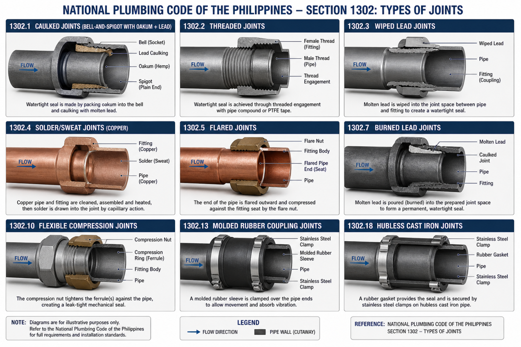
NPCP §1302 — Types of joints. Caulked, threaded, wiped, solder/sweat (copper), flared, burned-lead, flexible-compression, molded-rubber-coupling, and hubless cast-iron joints — each used per the material and application.
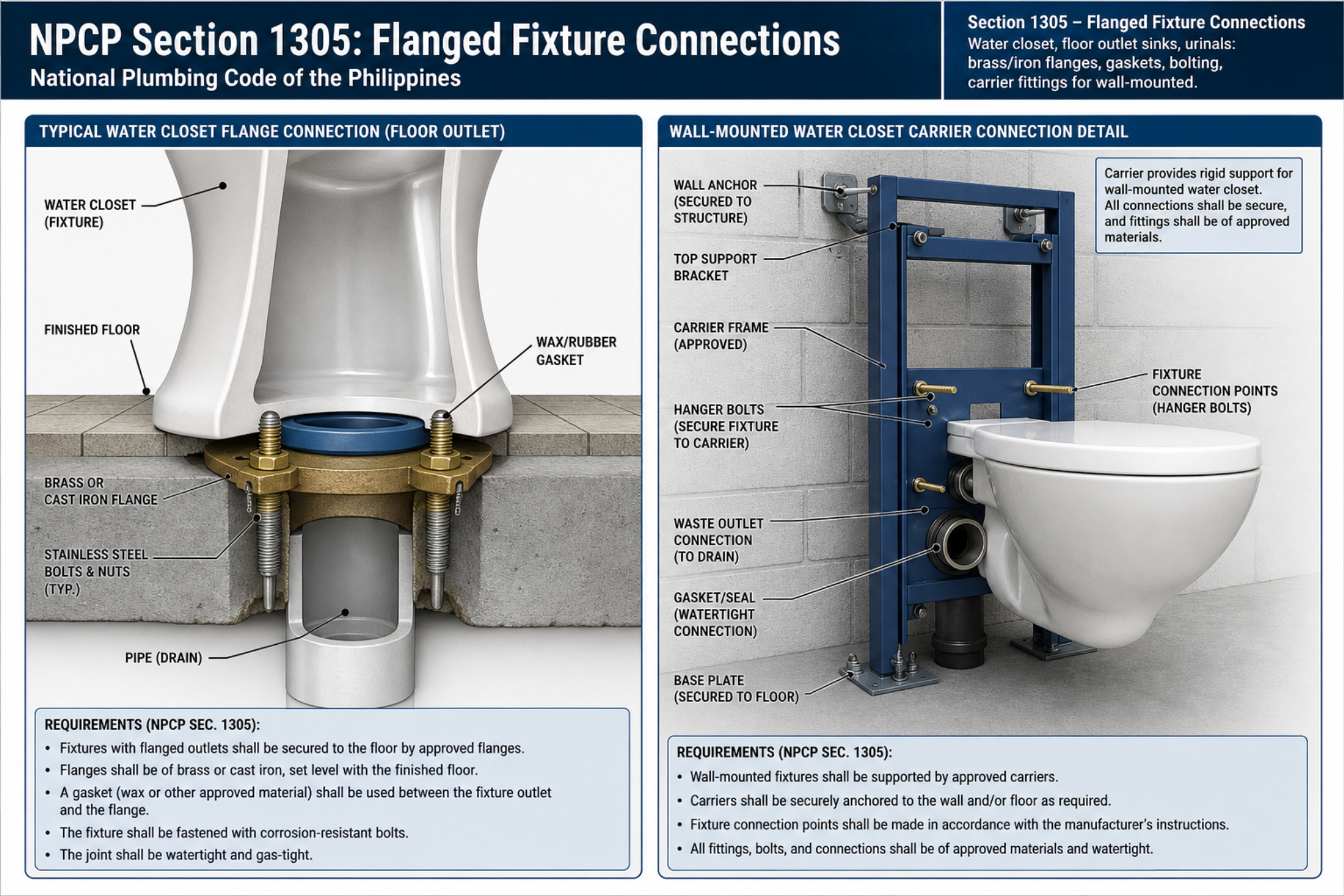
NPCP §1305 — Flanged fixture connections. Water-closet floor-outlet flange (brass/cast-iron ring, wax or approved gasket, corrosion-resistant bolts) and the wall-mounted WC carrier connection — watertight and gas-tight.
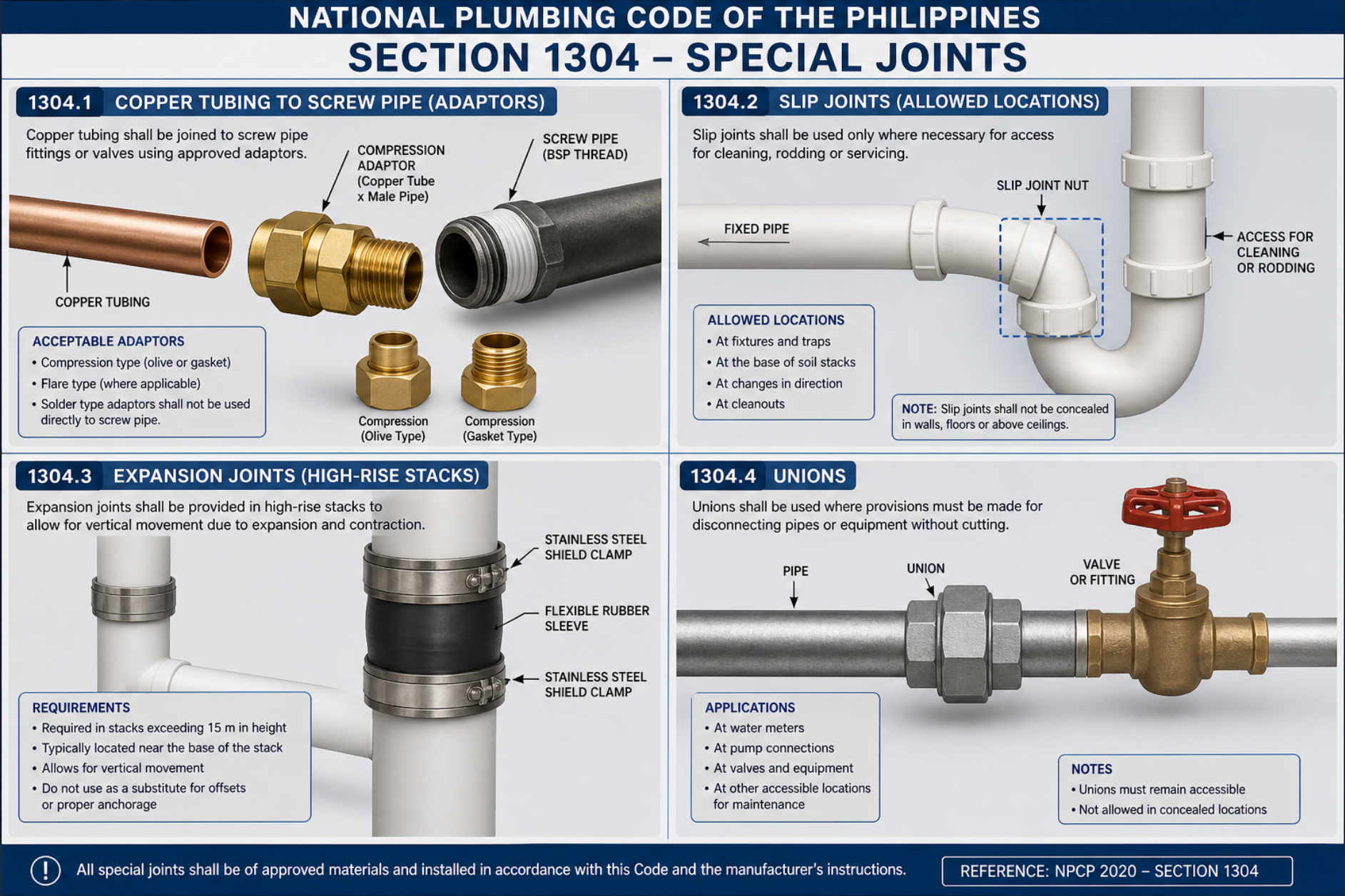
NPCP §1304 — Special joints. Copper-to-screw-pipe adaptors, slip joints (only in accessible locations), expansion joints for high-rise stacks, and unions where pipes/equipment must be disconnected.