Excreta Drainage System
Chapter 7 is the heart of drain design — it establishes the Drainage Fixture Unit (DFU) system for calculating pipe sizes, defines the sizing tables for horizontal branches, vertical stacks, and the building drain, and regulates special conditions like below-grade sumps, garage drains, and indirect wastes from equipment. Mastering this chapter allows you to size every drain pipe in a building from scratch.
Scope
What the Excreta Drainage System chapter covers
Chapter 7 applies to all Excreta Drainage System piping within a building — from the fixture trap outlet to the point of connection with the public sewer or approved private disposal system. It covers:
- Horizontal branch drains, floor drains, and fixture connections
- Vertical soil and waste stacks
- The building drain (horizontal collector at or below grade)
- The building sewer (from building foundation to street connection)
- Below-grade drainage via sump pits and ejector pumps
- Special waste conditions: garage drains, indirect wastes, acid wastes
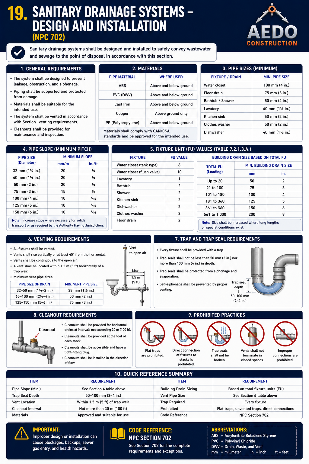
Sanitary (excreta) drainage system — design & installation. Every fixture trap discharges through properly sized, graded, and vented drain piping to the building drain and house sewer. Pipe is sized by drainage fixture units (DFU); minimum grade is 2% (20 mm/m) for ≤75 mm and 1% (10 mm/m) for ≥100 mm, with cleanouts at the required points and storm water kept completely separate. (NPC §702)
Design of Drainage System
Fundamental design principles
Every fixture shall discharge to a gravity drainage system wherever possible. Pumped (ejector) systems are only permitted where gravity drainage is physically impossible.
Every building with plumbing fixtures shall have a complete, separate Excreta Drainage System system. Two adjacent buildings shall not share a drainage system inside either building.
Drain pipes shall be sized and graded to maintain a minimum flow velocity of 0.6 m/s (2 fps) — the minimum velocity to keep solids in suspension and prevent deposits.
Fixture drains shall not connect to another fixture's trap arm or tailpiece — each fixture requires its own trap connection to the drain branch.
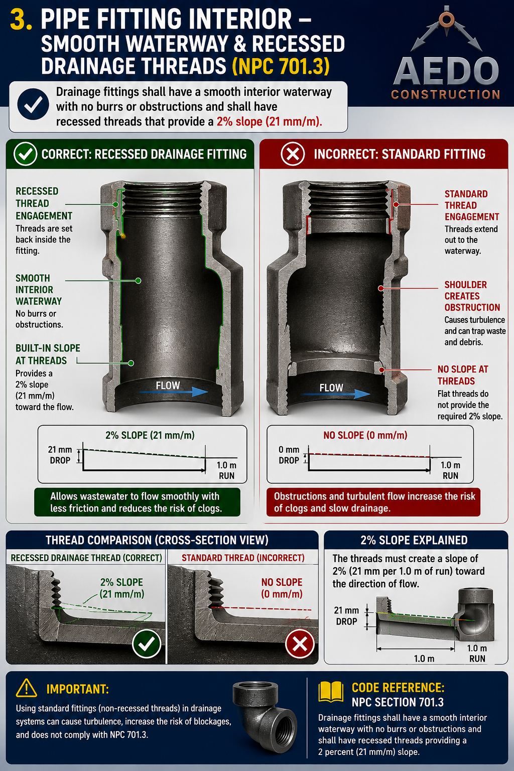
Per NPC §701.2.2, the threads of drainage fittings shall be tapped to allow a grade of two (2) percent, or 21mm per meter. Fittings on screwed pipe joints shall be of the recessed drainage type with burred ends reamed to the full bore of the pipe (§701.2.1).
Underground Drainage Pipe
Approved materials and installation for below-slab drain piping
| Material | Approved For Underground? | Notes |
|---|---|---|
| Cast Iron (hub-and-spigot or no-hub) | ✓ Yes | Most durable; preferred for building drain under slab |
| PVC-DWV (Schedule 40 or SDR35) | ✓ Yes | Most common in Philippine construction; solvent-welded joints |
| Vitrified Clay (VC) | ✓ Yes | For building sewer (outside building) only; coupled joints |
| ABS-DWV | ✓ Yes | Where approved by local authority |
| Galvanized Steel/Iron | ✗ No | Corrodes rapidly when buried; prohibited underground |
| Copper (DWV) | ⚠ Limited | Permitted but cost-prohibitive; requires insulation from concrete (alkali attack) |
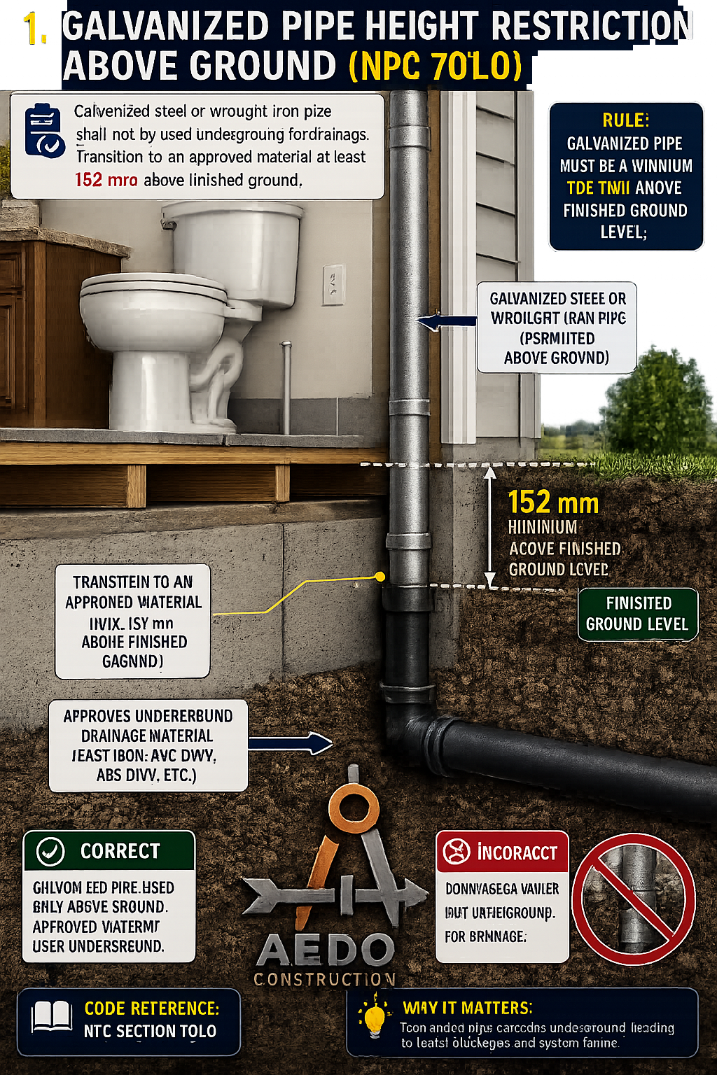
Per NPC §701.1.1, no galvanized wrought iron or galvanized steel pipe shall be used underground, and shall be kept at least 152mm above ground. Correct: galvanized pipe used only above grade; Incorrect: galvanized pipe running underground — causes rapid corrosion and pipe failure.
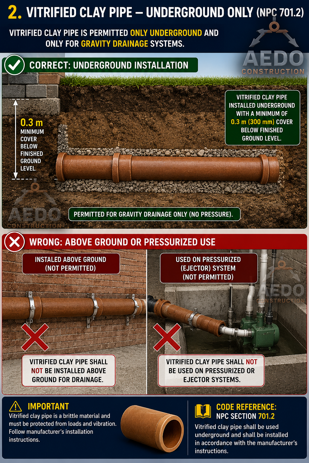
Per NPC §701.1.3, vitrified clay pipe or fittings for the building drain or sewer shall not be used above ground, or wherever piping is pressurized by a pump or ejector — they shall be kept at least 0.3 meter below finish ground level. Clay is a brittle material and must be protected from loads, vibration, and settlement.
Underground Pipe Material Lookup
Select a pipe material to check if it is approved for underground drainage use per §703.
Fixture Connections (Excreta Drainage)
How fixture drainage piping connects with approved fittings of the proper type and size
§704.2: Two fixtures set back-to-back, or side-by-side, within the distance allowed between a trap and its vent, may be served by a single vertical fitting, provided that such fixture wastes are separately into an approved double fitting, such as a double sanitary tee at the same level.
Drainage Fixture Unit (DFU) Values
Table 7-1 — Drainage demand load for each fixture type
| Fixture | Trap & Trap Arm Size (mm) | Drainage Fixture Unit (DFU) |
|---|---|---|
| Bathtubs | 38 | 2 |
| Bidets | 38 | 2 |
| Clotheswashers* | 51 | 2 |
| Dental units or cuspidors | 32 | 1 |
| Drinking fountains | 31 | 1 |
| Floor drains | 51 | 2 |
| Interceptors* for grease, oil, etc. | 51 | 3 |
| Interceptors* for sand, auto wash, etc. | 76 | 6 |
| Laundry tubs | 38 | 2 |
| Mobile home park traps (one for each trailer) | 76 | 6 |
| Receptors* (floor sinks); indirect waste receptors for refrigerators, coffee urns, water station, etc. | 38 | 1 |
| Receptors*, indirect waste receptors for commercial sinks, dishwashers, air washers, etc. | 51 | 3 |
| Shower, single stall | 51 | 2 |
| Shower*, gang (one unit per head) | 51 | 1 |
| Sinks, and/or dishwashers (residential), 51 mm min. waste | 38 | 2 |
| Sinks, bar, commercial, 51 mm min. waste | 38 | 2 |
| Sinks, bar, private, 38 mm min. waste | 32 | 1 |
| Sinks, commercial or industrial, schools, etc., including dishwashers, wash up sinks, and wash fountains 50.8 mm waste | 38 | 3 |
| Sink, flushing rim, clinic | 76 | 6 |
| Sink, service | 51 | 3 |
| Urinal, pedestal, trap arm only | 76 | 6 |
| Urinal, stall, separate trap | 51 | 3 |
| Urinal, wall-mounted, integral trap, trap arm only | 51 | 3 |
| Urinal, wall-mounted, blowout, integral trap, trap arm only | 76 | 6 |
| Urinal, wall-mounted, washdown or siphon-jet, integral trap, trap arm only | 51 | 2 |
| Urinal, wall-mounted, washout, separate trap, 50.8 mm min. waste | 38 | 2 |
| Wash basins, in sets | 38 | 2 |
| Wash basin (lavatory), single | 32 | 1 |
| Water closet,* private installation | 76 | 4 |
| Water closet, public installation | 76 | 6 |
* See NPC Sec. 180 / 214 NPC 1959 cross-reference, per Table 7-2 footnote.
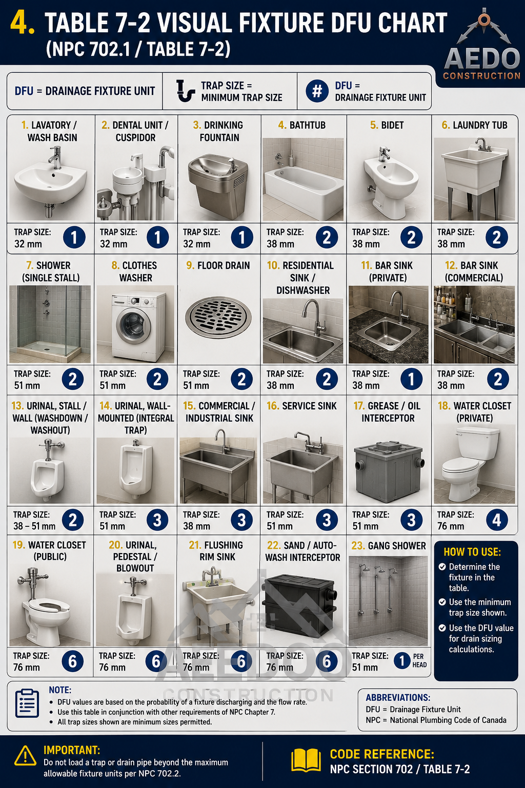
Visual DFU reference (per NPC Table 7-2): Lavatory / Drinking Fountain / Dental Unit = 1 DFU (32 mm trap); Bathtub / Bidet / Laundry Tub / Kitchen Sink / Dishwasher = 2 DFU (38 mm trap); Shower / Clothes Washer / stall Urinal = 2 DFU (51 mm trap); Water Closet — private = 4 DFU, public = 6 DFU (76 mm trap). Use the minimum trap size shown for each fixture.
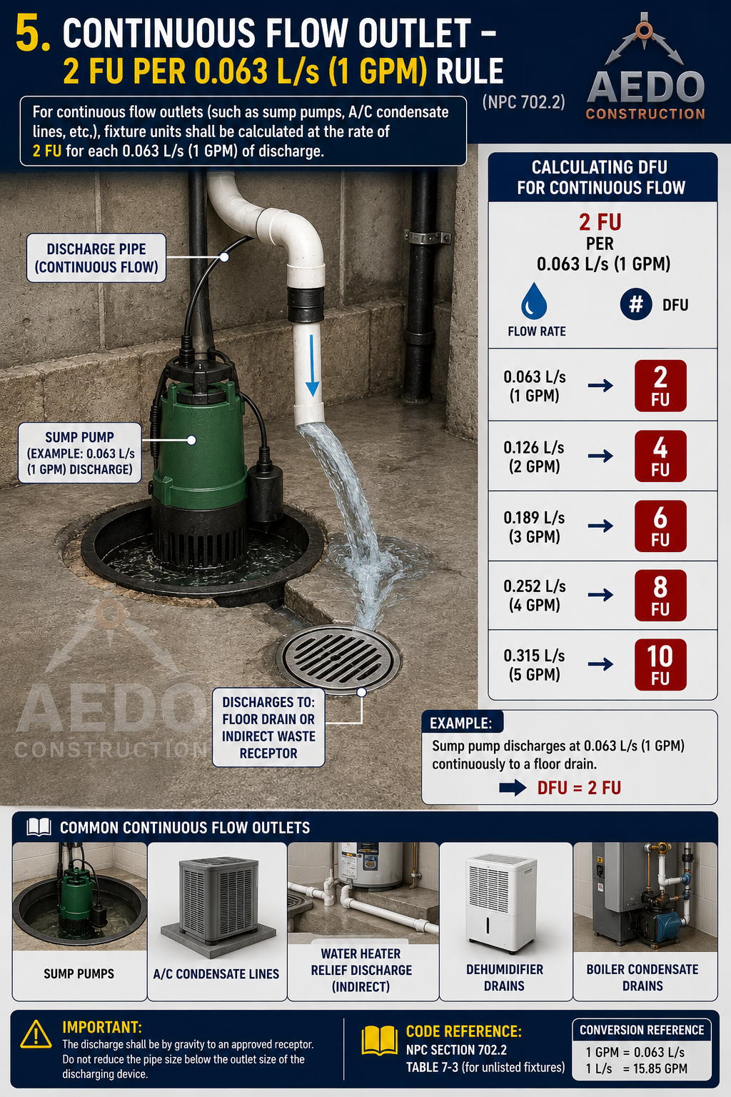
For continuous flow outlets (sump pumps, A/C condensate lines, etc.), fixture units are calculated at 2 FU per 0.063 L/s (1 GPM) of discharge. Examples: 0.063 L/s = 2 FU; 0.126 L/s = 4 FU; 0.189 L/s = 6 FU; 0.252 L/s = 8 FU; 0.315 L/s = 10 FU. Do not reduce pipe size below the outlet size of the discharging device.
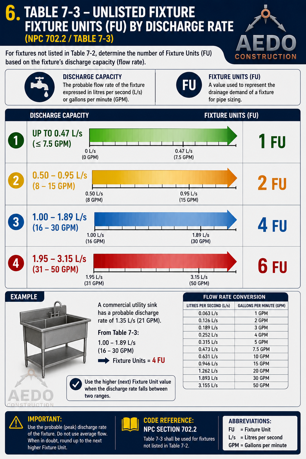
For fixtures not in Table 7-2, assign DFU based on discharge flow rate: ≤ 0.47 L/s (7.5 GPM) = 1 FU; 0.50–0.95 L/s (8–15 GPM) = 2 FU; 1.00–1.89 L/s (16–30 GPM) = 4 FU; 1.95–3.15 L/s (31–50 GPM) = 6 FU. Use the higher (next) FU value when flow falls between two ranges.
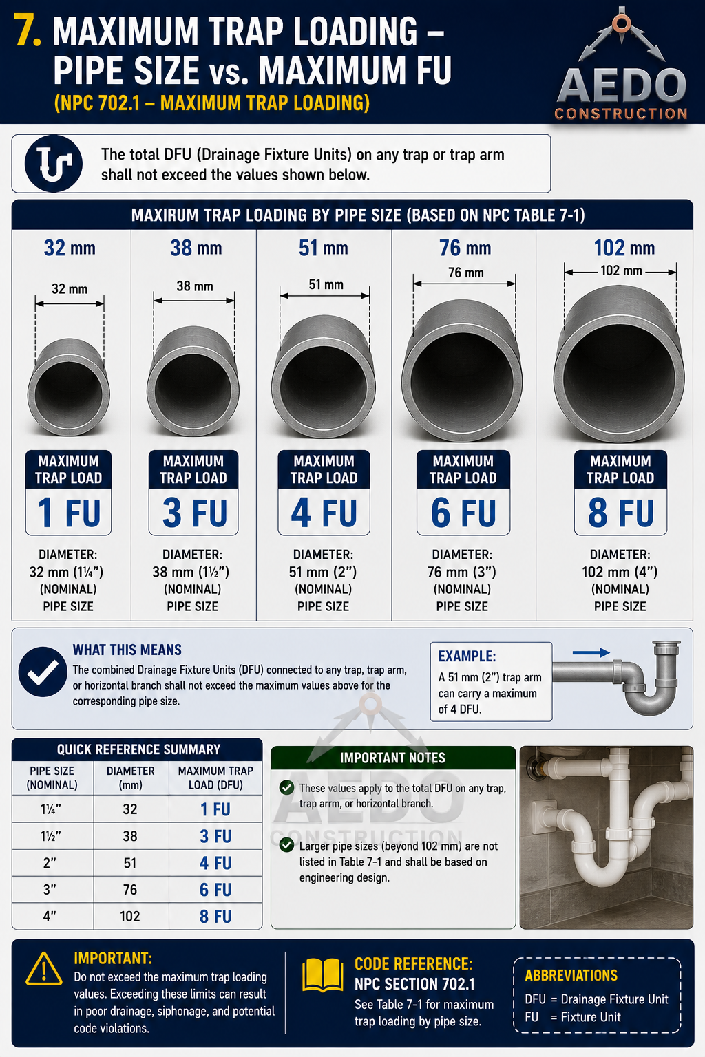
Maximum trap loading by pipe size: 32mm (1¼") = 1 FU; 38mm (1½") = 3 FU; 51mm (2") = 4 FU; 76mm (3") = 6 FU; 102mm (4") = 8 FU. The combined DFU connected to any trap, trap arm, or horizontal branch shall not exceed these values for the corresponding pipe size.
DFU Demand Counter
Add fixtures to tally total Drainage Fixture Units. Use the total with the §706 Drain Pipe Sizer below.
Drain Pipe Sizing
NPC Table 7-5 — Maximum fixture-unit loading & length of excreta drainage and vent piping
Table 7-5 — Maximum Fixture-Unit Loading & Maximum Length (Excreta Drainage & Vent Piping)
| Pipe Size | Max FU — Vertical Drain | Max FU — Horizontal Drain / Branch | Max Length — Vertical (m) | Max FU — Vent | Max Length — Vent (m) |
|---|---|---|---|---|---|
| 32 mm (1¼") | 1 | 1 | 14 | 1 | 14 |
| 38 mm (1½") | 2 (2) | 2 | 20 | 8 (3) | 18 |
| 51 mm (2") | 16 (3) | 8 (3) | 26 | 24 | 37 |
| 65 mm (2½") | 32 (3) | 14 (3) | 45 | 48 | 55 |
| 76 mm (3") | 48 (4) | 35 (4) | 65 | 84 | 65 |
| 102 mm (4") | 256 | 216 (5) | 91 | 256 | 91 |
| 127 mm (5") | 600 | 428 (5) | 119 | 600 | 119 |
| 152 mm (6") | 1,380 | 720 (5) | 155 | 1,380 | 155 |
| 203 mm (8") | 3,600 | 2,640 (5) | 228 | 3,600 | 228 |
| 254 mm (10") | 5,600 | 4,680 (5) | — | — | — |
Notes (per NPC Table 7-5): (1) Excluding trap arm • (2) Except sinks, urinals, and dishwashers • (3) Except 6-fixture-unit traps or water closets •
(4) Only four (4) water closets or six (6) fixture-unit traps are allowed on any vertical pipe or stack; not more than three (3) water closets or six (6) fixture-unit traps on any horizontal branch or drain •
(5) Horizontal values are based on a 2% (20.9 mm/m) slope. At a 1% (10.4 mm/m) slope, multiply the horizontal fixture-unit value by a factor of 0.8.
Horizontal drainage piping has no length limit. A vent shall not be smaller than 32 mm nor less than ½ the diameter of the drain to which it connects; fixture-unit load values for drainage and vent piping are computed from Tables 7-2 and 7-3, not to exceed ⅓ the total permitted vent length. When vents are increased one pipe size for their entire length, the maximum-length limits in this table do not apply.
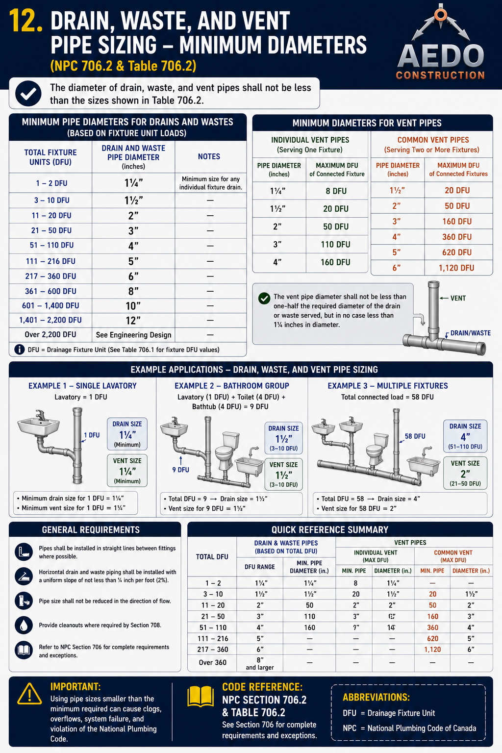
Minimum pipe diameters for drain, waste, and vent pipes based on total fixture units: 1–2 DFU = 1¼" (32mm); 3–10 DFU = 1½" (38mm); 11–20 DFU = 2" (51mm); 21–60 DFU = 3" (76mm); 61–216 DFU = 4" (102mm). Vent pipes: individual fixture vents minimum 1¼"; common vents (2+ fixtures) refer to sizing table. Vent pipe diameter shall not be less than half the required drain diameter it serves.
Drain & Vent Pipe Sizer — Table 7-5
Enter the total fixture-unit (FU/DFU) load and choose the piping function to find the minimum pipe size and maximum length per NPC Table 7-5. Use the DFU Counter in §705 above for your total.
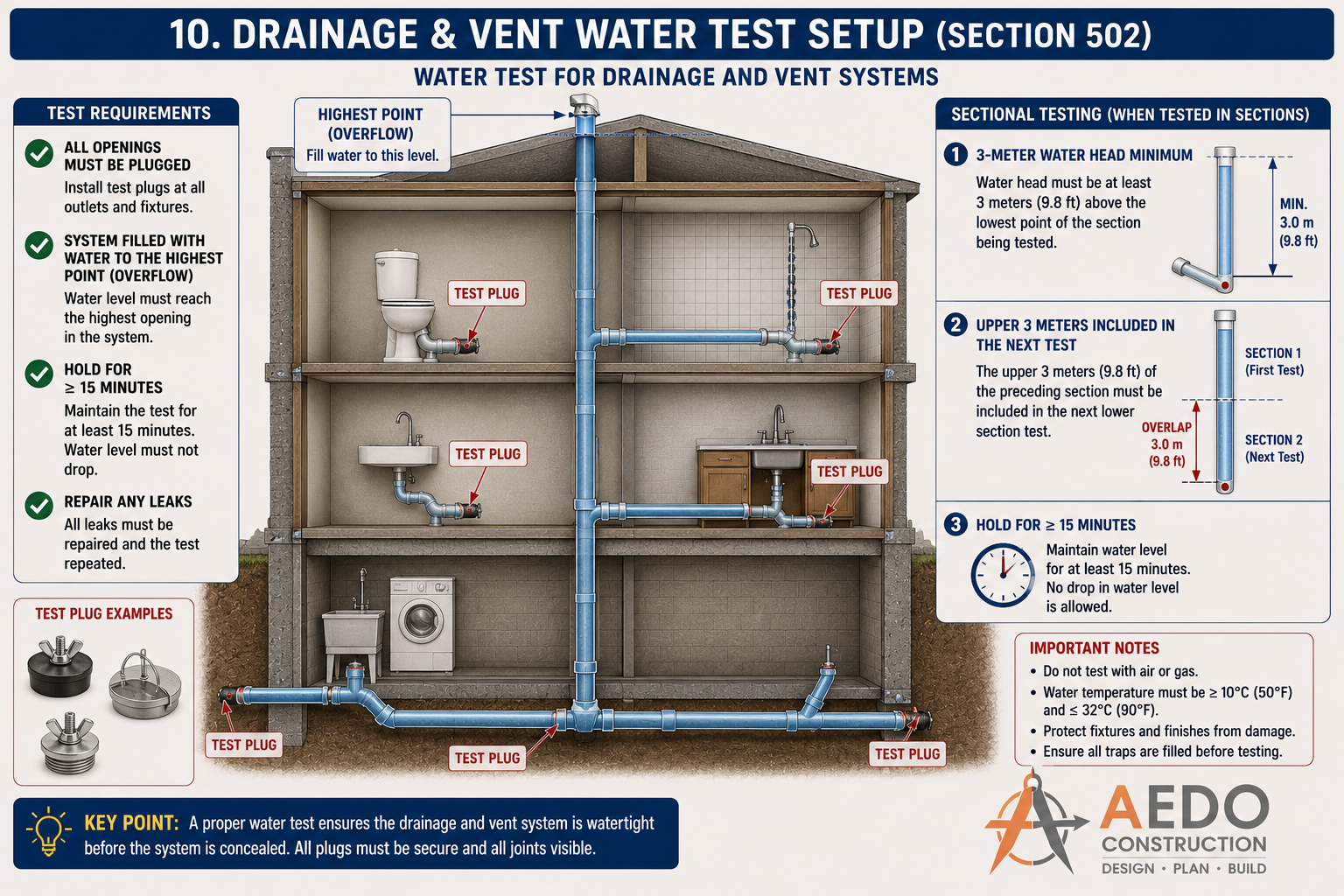
Drainage and vent water test: plug all openings, fill system to the highest point (overflow). Hold for minimum 15 minutes — water level must not drop. For sectional testing, maintain minimum 3-metre water head above the section being tested, with upper 3 metres of previous section included in the next test.
Offsets in Soil and Waste Stacks
How to handle changes in direction on vertical drainage stacks
| Offset Angle | Requirement | Notes |
|---|---|---|
| ≤ 45° from vertical | No change in stack size required at offset | Treated as continuation of stack; use long-radius fittings |
| > 45° from vertical (nearly horizontal) | Size offset as a horizontal drain using Table 7-2 | The offset and both vertical segments above/below may need enlarging |
| Any offset > 45° | Cleanout required at change of direction | Accessible cleanout fitting at each end of the offset |
Stack Offset Requirements
Select the offset angle from vertical to see the requirements per §707.
Branch Intervals
Definition and use of branch intervals in stack sizing
Branch intervals are used to count floors on a stack. The "maximum DFU per branch interval" column in Table 7-2 limits how many fixtures can connect at any single floor level — preventing overloading of the short section of stack between two consecutive floor connections.
A standard Philippine residential floor height of ~3.0m = 1 branch interval. If two toilets are on the same floor, their combined DFU must not exceed the "per-interval" limit for that stack size.
Stacks serving 10 or more branch intervals require yoke vents at every 10th interval (see Chapter 7 §712). A 10-storey building with 3m floors = 10 branch intervals = yoke vent required.
Building Drain
Definition, starting point, and sizing of the building horizontal drain
| Building Drain Requirement | Specification |
|---|---|
| Starting point | 0.6m inside outer face of foundation wall |
| Minimum size | 100mm (4") — cannot be smaller than the largest stack it receives |
| Minimum grade | 1% (10mm per meter) — or 2% where space permits |
| Cleanout at base of each stack | Required within 300mm of base — accessible |
| Cleanout at 90° changes of direction | Required wherever a branch exceeds 45° horizontal turn |
| Cleanout spacing (building drain) | Maximum 15m apart (for 100mm pipe); 30m for ≥150mm |
Building Drain Compliance Checker
Enter building drain specifications to verify compliance with §709 requirements.
Sump Pits and Ejector Pumps
Drainage for below-grade areas that cannot drain by gravity
Where plumbing fixtures are located below the level of the next upstream manhole cover on the public sewer, or where gravity drainage to the building drain is not possible, a sewage sump pit with ejector pump shall be installed.
| Requirement | Specification |
|---|---|
| Sump pit material | Pre-cast concrete, fiberglass, or polyethylene — watertight and gastight |
| Sump pit minimum size | 450mm diameter × 600mm depth (for residential); larger for commercial |
| Cover | Gastight, removable cover — prevents sewer gas release |
| Ejector pump | Submersible sewage pump with automatic float switch; duplex (2 pumps) for critical applications |
| Discharge pipe | Check valve required on discharge to prevent backflow when pump stops |
| Alarm | High-water alarm required for commercial/residential buildings with occupied below-grade spaces |
| Vent pipe | Sump pit shall be vented through a pipe extended outdoors or connected to building vent system |
Sump Pit & Ejector Requirements
Select the application type to see minimum specifications per §710.
Garage Floor Drains
Oil interceptor requirements for vehicle service areas
- Interceptor shall be sized for the maximum possible flow rate from hose bibb and floor washing.
- Cleanout access shall be provided at both inlet and outlet of the interceptor.
- The interceptor shall be pumped out regularly — grease/oil shall not be discharged into the sanitary sewer.
- Car wash facilities additionally require a recycle system or Class I interceptor approved by the local water authority.
Indirect Waste Piping
Equipment that must discharge through an air gap into the drain system
| Equipment / Device | Indirect Waste Required? | Recommended Receptor |
|---|---|---|
| Air conditioning condensate drain | Yes | Floor drain, sink, or approved receptor with air gap |
| Refrigerator / ice maker drain | Yes | Floor drain or open receptor |
| Commercial steamer / steam cooker | Yes | Floor sink or floor drain receptor |
| Dishwasher (commercial) | Yes | Floor sink or trapped receptor — air gap at sink drain |
| Domestic dishwasher | Air break | High loop or air gap fitting at sink drain connection |
| Drinking fountain waste | Yes | Floor drain with air gap at fountain outlet |
| Pressure relief valve discharge | Yes | Open sight drain — terminates above floor drain or outside |
Indirect Waste Requirement Lookup
Select the equipment type to check if an indirect waste connection is required per §712.
Special Wastes
Industrial, chemical, and hazardous waste disposal rules
| Waste Type | Required Treatment |
|---|---|
| Acid waste (laboratories, clinics) | Dilution/neutralization pit — pH 6–10 required before discharge |
| Grease-laden waste (commercial kitchens) | Grease interceptor sized per anticipated flow — see Chapter 9 |
| Radioactive waste (hospitals, research) | Special holding tank — must comply with PNRI (Philippine Nuclear Research Institute) regulations |
| Infectious waste (hospitals) | Disinfection/sterilization required; DOH-compliant disposal |
| Photographic/X-ray waste (silver compounds) | Silver recovery unit required before discharge |
Special Waste Treatment Lookup
Select the waste type to see the required pre-treatment before discharge per §713.