
Septic Tanks
B.1–B.11 · Septic tank design, capacity sizing, setback distances, absorption fields, percolation testing, and subsurface disposal systems for buildings not connected to public sewers.
Appendix B covers the design, sizing, and installation of septic tank systems for buildings not served by public sewer systems. This is particularly critical in rural areas of the Philippines, low-density subdivisions, and island communities. The chapter covers everything from tank capacity to soil absorption fields and percolation testing.
Scope & General Requirements
B.1. Scope. The provisions of this Appendix govern the design, construction, and installation of individual sewage disposal systems which are not connected to a public sewer.
B.2. General. A private sewage disposal system (septic tank with absorption field, or other approved system) may be used wherever a building's drainage cannot be connected to a public sewer (see Chapter 3, §305).
Septic Tank Design & Construction
B.5. Septic tanks shall be watertight structures constructed of durable materials not subject to excessive corrosion. Every septic tank shall be provided with a cover having a manhole not less than 508mm in diameter (B.5.5). The invert of the inlet pipe shall be at least 50.8mm above the invert of the outlet pipe (B.5.7).
The inlet shall be provided with a sanitary tee or baffle extending not less than 304.8mm below the liquid surface (B.5.7). The outlet shall be provided with a sanitary tee or baffle extending below the liquid surface to within one-third of the liquid depth from the bottom.
[CH10-DIAGRAM-A] — Septic tank cross-section with baffle detail
Septic Tank Capacity
Septic tank capacity is governed by NPC Appendix B — Private Sewage Disposal Systems, Table B-2 (Capacity of Septic Tanks). Minimum liquid capacity is scheduled by number of bedrooms (single-family dwellings), number of one-bedroom units (multi-dwelling/apartments), or maximum drainage fixture units served per Table 7-2 (other occupancies) — whichever governs. Septic tank sizes in Table B-2 already include sludge-storage capacity and the connection/disposal of domestic food-waste units, with no further volume increase required for that purpose.
| Single-Family Dwellings — Bedrooms | Multiple Dwelling Units / Apartments (1-BR each) | Other Uses — Max. DFU Served (Table 7-2) | Min. Capacity — Gallons | Min. Capacity — Liters |
|---|---|---|---|---|
| 1 or 2 | — | 15 | 750 | 2,838 |
| 3 | — | 20 | 1,000 | 3,785 |
| 4 | 2 units | 25 | 1,200 | 4,542 |
| 5 or 6 | 3 | 33 | 1,500 | 5,677.5 |
| — | 4 | 45 | 2,000 | 7,570 |
| — | 5 | 55 | 2,250 | 8,516.3 |
| — | 6 | 60 | 2,500 | 9,462.5 |
| — | 7 | 70 | 2,750 | 10,408.8 |
| — | 8 | 80 | 3,000 | 11,355 |
| — | 9 | 90 | 3,250 | 12,301.3 |
| — | B | 100 | 3,500 | 13,247.5 |
Beyond the table: extra bedroom (single-family, beyond 6) — add 567.8 L each · extra dwelling unit (beyond 10) — add 946.3 L each · extra fixture unit (beyond 100 DFU) — add 94.6 L per fixture unit. Note: sizes shown already include sludge-storage capacity and domestic food-waste connection/disposal — no further volume increase is required for those purposes.
| Type of Occupancy | Flow Rate |
|---|---|
| Schools — staff & office | 75.7 L per person |
| Schools — elementary students | 56.8 L per person |
| Schools — intermediate & high school students | 75.7 L per student (+18.9 L/student with gym & showers; +11.4 L/student with cafeteria) |
| Schools — boarding (total waste) | 378.5 L per person |
| Offices | 75.7 L per employee |
| Restaurants / cafeterias | 75.7 L/employee + 26.5 L/customer (toilet) + 22.7 L/meal (kitchen waste) — add 3.8 L/meal for garbage disposal, 7.6 L/customer for cocktail lounge |
| Hospitals | 946.3 L per bed (94.6 L/bed kitchen-only · 151.4 L/bed laundry-only) |
| Hotels (no kitchen waste) | 227.1 L per bed space (2-person) |
Table B-3 lists flow rates for many more occupancy types (airports, camps, churches, factories, institutions, laundries, motels, parks/RV sites, service stations, stores, etc.) — the rows above cover the occupancies most commonly encountered in Philippine residential and commercial projects. Because actual flow varies by situation, the Code allows the designer to evaluate each case and adjust figures with the concurrence of the Administrative Authority.
Septic Tank & Absorption Field Sizer
Estimate the minimum septic tank capacity per NPC Appendix B Table B-2, then the required absorption-field (leaching) area for your soil type per Tables B-4 & B-5.
Setback Distances
Minimum horizontal clearances for sewage-disposal-system components are scheduled in NPC Appendix B, Table B-1 (Location of Sewage Disposal System). Each component — building sewer, septic tank, disposal (absorption) field, and seepage pit/cesspool — has its own required clear distance from buildings, property lines, water-supply wells, streams, trees, and other system components. For the septic tank specifically, the minimum clear distances are:
15.2 m from a water-supply well or suction line (may govern down to 7.6 m for piping built of materials approved for use within a building — Table B-1 Note 3)
15.2 m from a stream or natural body of water
1.5 m from any building, structure, porch, breezeway, carport, or similar appurtenance
1.5 m from a property line adjoining private property
1.5 m from an on-site domestic water service line, seepage pit/cesspool, or disposal field
3 m from trees, and 3 m from a pressure public water main
Where a disposal field or seepage pit sits on sloping ground, the minimum horizontal distance between any part of the leaching system and the ground surface shall be 4.6 m (Table B-1, general note).
[CH10-DIAGRAM-B] — Selected septic-tank clearances per NPC Appendix B, Table B-1 (not to scale — see full table below for all components & distances)
| Required Clear Distance From | Building Sewer | Septic Tank | Disposal Field | Seepage Pit / Cesspool |
|---|---|---|---|---|
| 1. Buildings or structures (1) | 0.6 m | 1.5 m | 2.4 m | 2.4 m |
| 2. Property line adjoining private property | Clear (2) | 1.5 m | 1.5 m | 2.4 m |
| 3. Water-supply wells | 15.2 m (3) | 15.2 m | 30.5 m | 45.7 m |
| 4. Streams | 15.2 m | 15.2 m | 15.2 m | 30.5 m |
| 5. Trees | — | 3 m | — | 3 m |
| 6. Seepage pits or cesspools | — | 1.5 m | 1.5 m | 3.7 m |
| 7. Disposal field | — | 1.5 m | 1.2 m | 1.5 m |
| 8. On-site domestic water service line | 0.3 m (5) | 1.5 m | 1.5 m | 1.5 m |
| 9. Distribution box | — | — | 1.5 m | 1.5 m |
| 10. Pressure public water main | 3 m (6) | 3 m | 3 m | 3 m |
General note: where disposal fields and/or seepage pits are installed on sloping ground, the minimum horizontal distance between any part of the leaching system and the ground surface shall be 4.6 m.
(1) Includes porches and steps (covered or uncovered), breezeways, roofed porte-cochères, roofed patios, carports, covered walks/driveways, and similar appurtenances.
(2) See also §314 of this Code.
(3) Drainage piping must clear domestic water-supply wells by at least 15.2 m; this may be reduced to not less than 7.6 m where the piping is built of materials approved for use within a building.
(4) Add 0.6 m for each additional 0.3 m of depth beyond 0.3 m below the bottom of the drain line (see also §B-6 of this Appendix).
(5) See §1208 of this Code.
(6) For parallel construction; for crossings, Administrative Authority approval is required. These minimum clear horizontal distances also apply between the disposal field/seepage pits and the ocean's mean higher-high-tide line.
Absorption (Leach) Fields & Distribution
B.6. Absorption Field. Where soil conditions are suitable, the liquid effluent from a septic tank may be disposed of by means of an absorption field consisting of perforated pipe laid in a bed of gravel. The minimum diameter of absorption field piping shall be 100mm (4 in.) and the minimum grade shall be 25 mm/m (2.5%), per the grade table in B.6.9.
The total length of absorption field piping required shall be determined from soil percolation tests (B.4). The minimum area of the absorption field shall not be less than determined from the percolation test results, using the required square meter of trench bottom per liter of daily sewage flow.
| Soil Type | Required Leaching Area (m² per liter of tank capacity) | Max. Absorption Capacity (L per m² of leaching area, 24-hr period) |
|---|---|---|
| 1. Coarse sand or gravel | 0.005 | 203.7 |
| 2. Fine sand | 0.006 | 162.9 |
| 3. Sandy loam or sandy clay | 0.010 | 101.9 |
| 4. Clay with considerable sand or gravel | 0.022 | 44.8 |
| 5. Clay with small amount of sand or gravel | 0.029 | 33.8 |
| Required Leaching Area / Tank Capacity (m²/L) | Maximum Septic Tank Size Allowable (Liters) |
|---|---|
| 0.005 – 0.006 | 28,387.5 |
| 0.010 | 18,925 |
| 0.022 | 13,247.5 |
| 0.029 | 11,355 |
How to use Tables B-4 & B-5 together: identify the soil type from the percolation/soil test, read its required leaching-area ratio (m² per liter of tank capacity) from Table B-4, multiply by the tank's liquid capacity to get the minimum absorption-field area — then check Table B-5 to confirm that ratio doesn't cap the maximum allowable tank size for that soil. Where soil is poorer than Type 5 (very slow absorption / high water table / shallow rock), the Administrative Authority may require an alternative disposal method (e.g., aerobic treatment unit, mound system, or connection to a community system) instead of a conventional absorption field.
Percolation Test Procedure
B.4. Before designing an absorption field, a soil percolation test shall be conducted in the area proposed for absorption field installation, subject to the approval of the Administrative Authority, and classified against Table B-4 (Design Criteria of Five Typical Soils).
Dosing Chambers, Seepage Pits & Other Disposal
B.7. Where dosing is required, dosing chambers shall be provided with automatically operated siphons or pumps to distribute effluent intermittently throughout the absorption field.
Seepage Pits. A seepage pit consists of a covered pit with open-jointed lining through which septic tank effluent may seep or leach into the surrounding soil. The minimum diameter shall be 2.2 m (B.7.3) and minimum depth below inlet shall be 3 m (B.7.6).
Per Table B-1, a seepage pit/cesspool requires substantially larger clearances than a septic tank because effluent leaches directly into the soil with less pre-treatment: 45.7 m from any water-supply well, 30.5 m from a stream, 2.4 m from a building or property line, 3.7 m from any other seepage pit/cesspool, and 3 m from trees. Like septic tanks and disposal fields, a 4.6 m clearance from the ground surface applies on sloping sites.
Seepage pits are an alternative where a single large pit is used when trench-type absorption fields are impractical. Min. 2.2 m dia., min. 3 m deep below the inlet pipe.
Single deep pit, 2.2 m min. dia. Better for small lots. Still requires soil perc test. Not for unstable soils or high water table.
Distributed system with larger total soil contact area. Preferred method. More effective treatment. Required when soil is marginal.
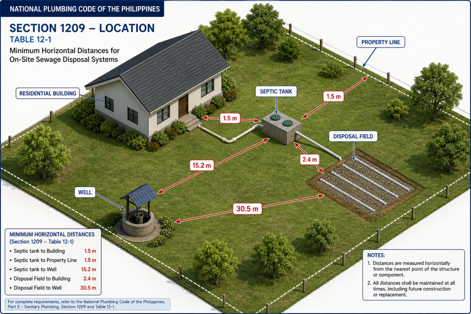
NPCP Appendix B, Table B-1 — Septic setbacks. Minimum horizontal distances: septic tank ≥1.5 m from building & property line and ≥15.2 m from a well; disposal field ≥2.4 m from building and ≥30.5 m from a well.
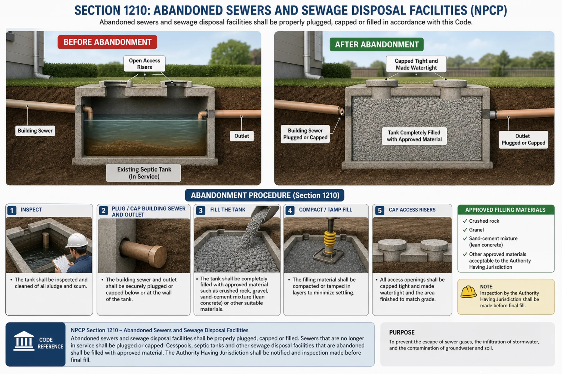
NPC Appendix B — Abandoned sewers & tanks. Abandoned septic tanks/cesspools shall be pumped, then completely filled with approved material (crushed rock, gravel, sand-cement) and the building sewer plugged/capped watertight.
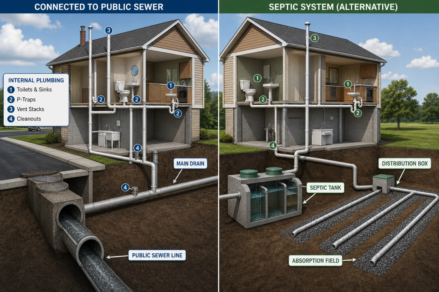
Public sewer vs. private septic. Where a public sewer is available the building connects to it; otherwise an approved on-site septic tank and disposal field is used (see §1201 and the setbacks above).