Inspection & Testing
Chapter 5 governs how plumbing work is verified before it is concealed and before the building is occupied. No drainage, vent, or water-supply piping may be covered until it has been inspected and successfully tested. The two cornerstone tests are the water test and the air test on the drainage and vent (DWV) system, plus the pressure test on the potable supply (see Chapter 6). This chapter also covers maintenance, existing construction, and the health-and-safety duty behind every inspection.
Inspection Required
All new plumbing work must be inspected before use and before concealment
All plumbing systems — new installations, extensions, alterations, and repairs covered by a plumbing permit — shall be inspected by the authority having jurisdiction (the Building Official, through the plumbing inspector) before the system is used and before any portion is covered or concealed.
No piping shall be covered by slab, backfill, wall finish, or furring until inspected and tested.
The Registered & Licensed Master Plumber (RLMP) is responsible for requesting inspection at the correct stages.
The work must remain accessible and exposed until the inspector approves it.
Corrected defects must be re-tested and re-inspected before cover.
Notice & Access for Inspection
The work must be ready, exposed, and tested when the inspector arrives
When the work is ready for inspection, the permit holder shall notify the Building Official and provide safe access to all parts of the installation. It is the permit holder's responsibility — not the inspector's — to:
- Have the system under test (water or air) at the time of inspection;
- Provide ladders, lights, and access to concealed spaces, shafts, and ceilings;
- Furnish any required testing equipment (test plugs, gauges, pumps);
- Remove or replace any concealment installed without approval, at no cost to the jurisdiction.
Rough-in (Concealment) Inspection
Performed after piping is installed but before it is concealed
The rough-in inspection covers all drainage, vent, and water-supply piping before it is buried, embedded in concrete, or hidden by finishes. It is usually broken into two stages:
Building drain and underground piping inspected and tested before backfill or slab pour.
Stacks, branches, and vents inspected and tested before walls and ceilings are closed.
At rough-in the inspector verifies pipe materials, sizing, grade/slope, support and hangers, change-of-direction fittings, trap arms, vent connections, and cleanout locations — then witnesses the water or air test.
Final Inspection
Performed when the system is complete and fixtures are set
The final inspection takes place after all fixtures are installed, trapped, and connected, and the system is ready for use. The inspector confirms:
- Every fixture is properly trapped and vented, with the correct trap-seal depth;
- The final (smoke or water) test holds and there is no sewer-gas leakage;
- Cleanouts are accessible and water supply delivers adequate pressure/flow;
- Cross-connection controls and backflow devices are in place and operable.
Water Test — Drainage & Vent System
The standard proof test for the DWV system
The water test is applied to the drainage and venting system either in its entirety or in approved sections. All openings are tightly plugged except the highest, and the system is filled with water to produce a head of pressure on every joint.
At least 3 m (10 ft) of water head on the section under test — so no point is under less than this pressure.
Water level held for a minimum of 15 minutes with no drop before and during inspection.
No leakage at any joint and no measurable drop in water level.
Tall buildings may be tested floor-by-floor, each section still seeing the minimum head.
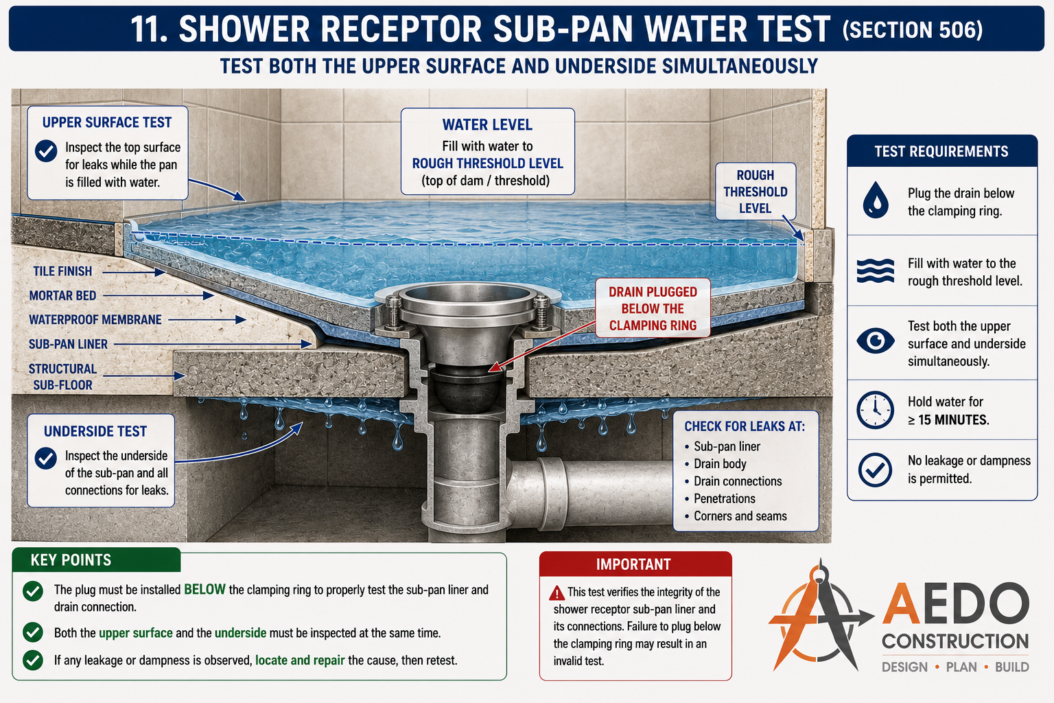
Shower receptor sub-pan water test. A worked example of the §505 water test applied to a shower pan: the drain is plugged below the clamping ring, the pan is filled to the rough threshold level, and both the upper surface and the underside are inspected for leaks for at least 15 minutes before the pan is covered.
Air Test
An approved alternative to the water test
Where a water test is impractical, an air test may be used. All openings are plugged and the system is pressurised with air through a gauge.
- Apply a uniform air pressure of 34.5 kPa — sufficient to balance a 254 mm (10 in) column of mercury — to the whole DWV system;
- The pressure must hold without loss for at least 15 minutes with no added air;
- A pressure drop indicates a leak that must be located, repaired, and re-tested.
DWV Test Requirements Checker
Select the test method to see the required pressure/head, hold time, and acceptance criteria under Chapter 5.
Maintenance & Existing Construction
Keeping installed systems safe and serviceable
All plumbing systems and equipment, both new and existing, shall be maintained in a safe and sanitary condition by the owner. Existing systems lawfully installed under earlier codes may remain in use provided they are not unsafe, unsanitary, or a nuisance.
- Defective, leaking, or dangerous installations must be repaired or replaced;
- Alterations and additions to existing systems are inspected and tested as new work;
- The Building Official may order correction of any existing condition found hazardous to health or safety.
Health & Safety
The purpose behind every inspection and test
Inspection and testing exist to protect public health, safety, and welfare. The plumbing system must, at all times, prevent:
No cross-connection between potable supply and any source of pollution.
Intact trap seals and proper venting keep sewer gases out of occupied spaces.
Watertight joints prevent structural damage, mold, and unsanitary conditions.
No condition that endangers life, health, or the safety of occupants.
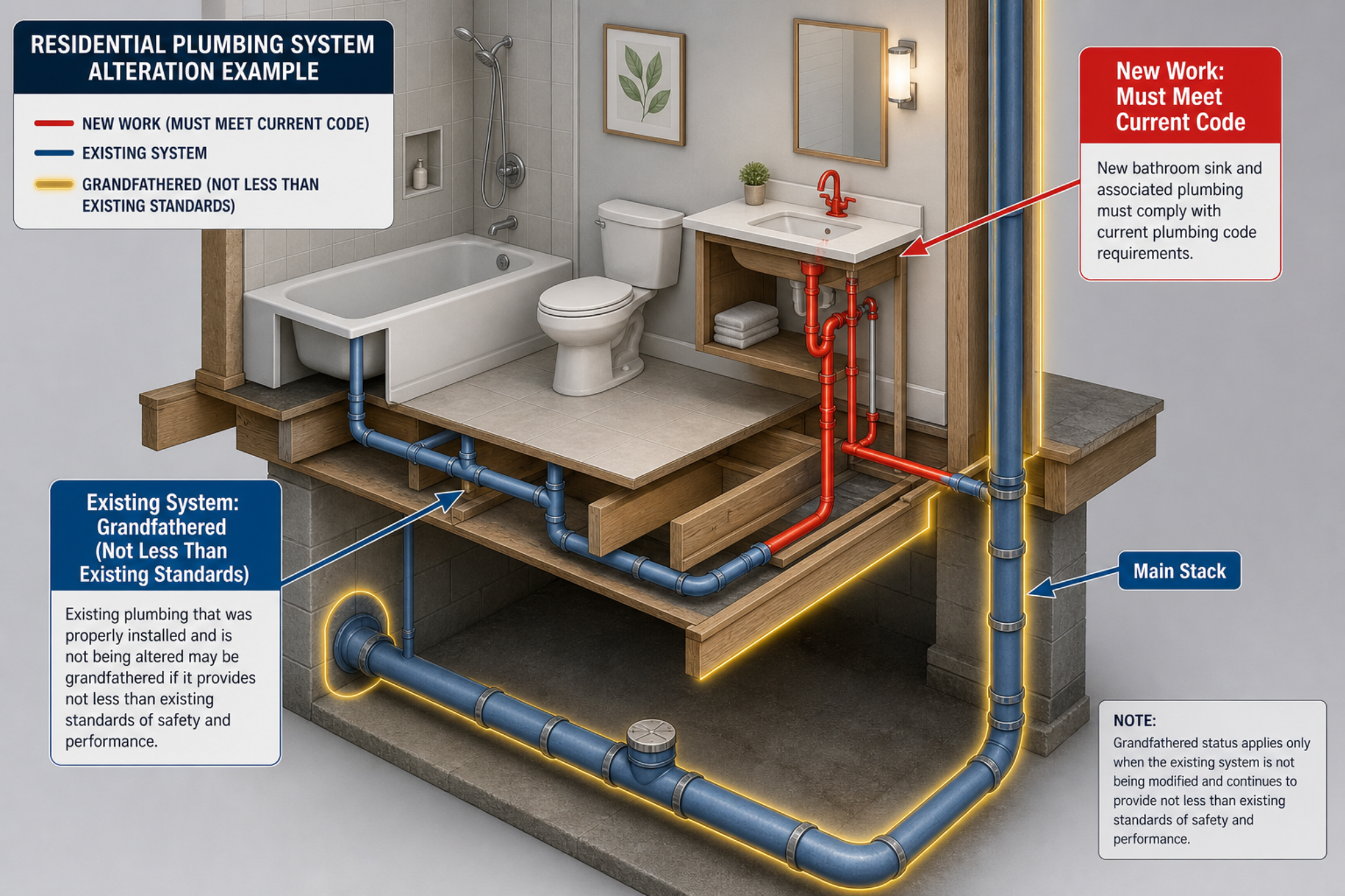
Existing & altered systems (§507). When a system is altered, the new work must meet the current code, while properly installed existing plumbing may remain (grandfathered) as long as it is not less than existing standards of safety and performance.